
Pen withdrawal trigger mechanism of electric pencil sharpener

A trigger mechanism and pencil sharpening technology, which is applied in the mechanical field, can solve the problems of electric pencil sharpener function influence, micro switch sensitivity reduction, and no automatic pen retracting function, so as to achieve high sensitivity, fast response time, and avoid being affected damage effect

Active Publication Date: 2016-04-27
SUNWOOD HLDG GROUP
View PDF7 Cites 0 Cited by
  • Summary
  • Abstract
  • Description
  • Claims
  • Application Information

AI Technical Summary

Problems solved by technology

[0004] Although the automatic pen feeding device of the above-mentioned electric pencil sharpener replaces the original manual pen feeding method and improves the automatic function of the electric pencil sharpener, since the stop of the motor is realized by pressing the slider on the tip of the pencil to touch the micro switch, Moreover, it does not have the function of automatically withdrawing the pen, so as long as the user does not push the pencil out, the pencil tip will always press the slider to touch the micro switch
Sometimes the user inserts the pencil to deal with other affairs and forgets to pull out the pencil. If things go on like this, it will easily cause the sensitivity of the micro switch to decrease, and it will be difficult to reset, which will affect the function of the electric pencil sharpener.

Method used


Image

  • Pen withdrawal trigger mechanism of electric pencil sharpener
  • Pen withdrawal trigger mechanism of electric pencil sharpener
  • Pen withdrawal trigger mechanism of electric pencil sharpener

Examples


Embodiment 1

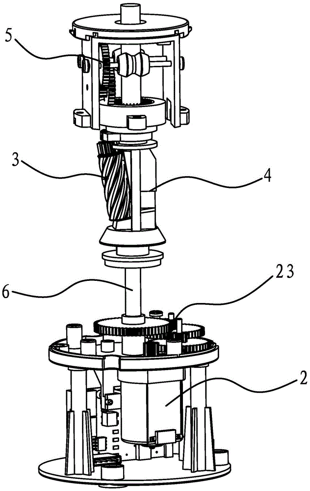
[0040] like figure 1 and Figure 8 As shown, a pen withdrawal trigger mechanism of an electric pencil sharpener is arranged in the casing 1 of the electric pencil sharpener. The casing 1 of the electric pencil sharpener is cylindrical, the bottom of the casing 1 is provided with a power interface 24, the casing 1 is provided with a motor 2, a pen holder 4 connected with a planing assembly 3 and a pen feeding assembly 5, and a motor 2 A drive shaft 6 is arranged between the pen holder 4, and a transmission gear set 23 is arranged between the output shaft of the motor 2 and the transmission shaft 6. When the motor 2 rotates, the drive shaft 6 can be driven to rotate by the transmission gear set 23, and the pen holder 4 rotates. Afterwards, the pen feeding assembly 5 can be driven into the pen and the planing assembly 3 can be driven to plan the pencil.

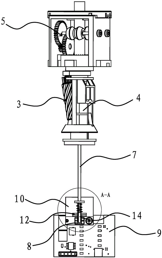
[0041] like figure 2 As shown, the triggering mechanism for retracting the pen includes the ejector rod 7 arranged in the ...


PUM


Abstract

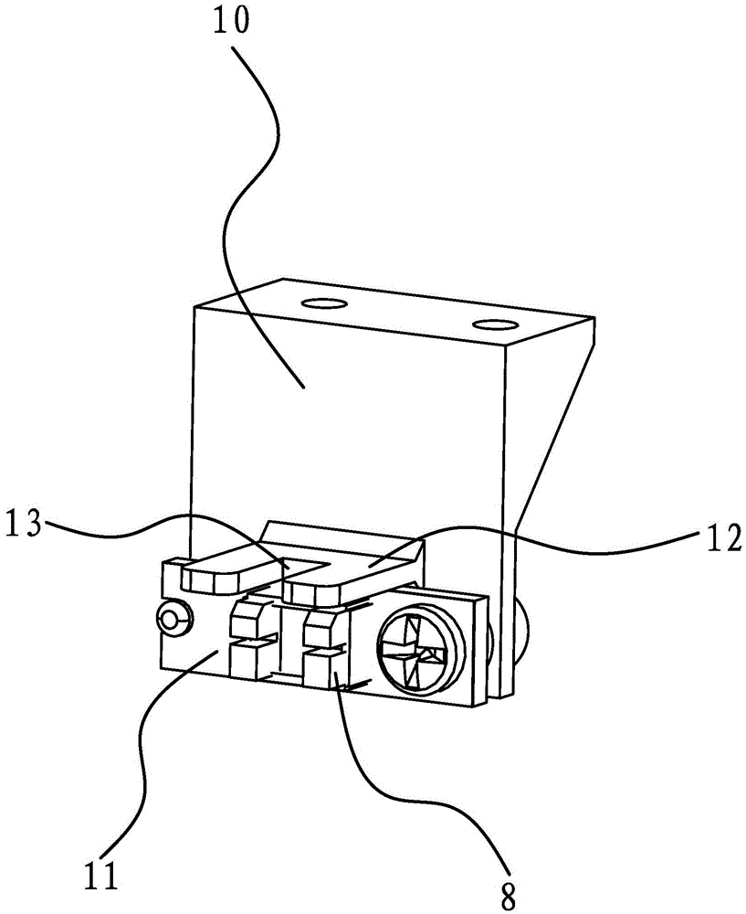
The invention provides a pencil retreating trigger mechanism of an electric pencil sharpener and belongs to the technical field of machinery. The problem that an existing electric pencil sharpener cannot allow a pencil to retreat automatically is solved. The pencil retreating trigger mechanism is arranged in a case of the electric pencil sharpener, a motor, a pencil holder connected with a sharpening component and a pencil entering component are arranged in the case, a transmission shaft is arranged between the motor and the pen holder, the pencil retreating trigger mechanism comprises an ejection rod arranged in the transmission shaft and a counter-emitting type optoelectronic switch and a control chip arranged in the case, the counter-emitting type optoelectronic switch and the motor are electrically connected with the control chip, and the upper end of the ejection rod extends into the pen holder. After the pencil is sharpened, the lower end of the ejection rod can be pushed by a pencil point to move downwards and trigger the counter-emitting type optoelectronic switch. A timing module is integrated on the control chip, when the counter-emitting type optoelectronic switch is triggered, the timing module starts to perform timing, and the control chip controls the motor to rotate reversely when time kept by the timing module reaches a preset value. The pencil retreating trigger mechanism has the advantages of high flexibility, fast response, timely pencil retreating and the like.

Description

technical field [0001] The invention belongs to the technical field of machinery, and relates to an electric pencil sharpener, in particular to a pen withdrawal trigger mechanism of the electric pencil sharpener. Background technique [0002] Electric pencil sharpener is a very common office stationery in the office. Today, the pace of work is accelerating and people are constantly pursuing convenience and efficiency in their work. brings great convenience. It generally includes a housing assembly, a tool holder assembly, a drive assembly and a power supply assembly, wherein: the knife holder assembly, the drive assembly, and the power supply assembly are arranged in the inner space of the housing assembly; the drive assembly is composed of a motor and a gear box, etc. The power is transmitted to the knife holder, and the hob on the knife holder is driven to automatically plan the pencil. After the planing is completed, the micro switch can be touched by the tip of the penc...

Claims


Application Information

Patent Timeline
Patent Type & Authority Patents(China)
IPC IPC(8): B43L23/00
Inventor 林夏森
Owner SUNWOOD HLDG GROUP
Learn More