
Coupled feeding inverted F antenna

A technology of coupling feed and antenna, which is applied in the field of coupled feed inverted F antenna, can solve the problems of poor omnidirectional performance of inverted F antenna, and achieve the effect of improving direction out-of-roundness, improving efficiency, and improving out-of-roundness

Active Publication Date: 2014-11-12
TAIXING DONGSHENG ELECTRONICS EQUIP FACTORY
View PDF8 Cites 4 Cited by
  • Summary
  • Abstract
  • Description
  • Claims
  • Application Information

AI Technical Summary

Problems solved by technology

[0003] Aiming at the disadvantage of the poor omnidirectional performance of the inverted F antenna in the prior art, the present invention provides a coupling-fed inverted F antenna with a simple structure, which can effectively improve the out-of-roundness of the antenna direction and improve the omnidirectional performance

Method used


Image

  • Coupled feeding inverted F antenna

Examples


Embodiment Construction

[0013] The present invention will be further described below in conjunction with drawings and embodiments.

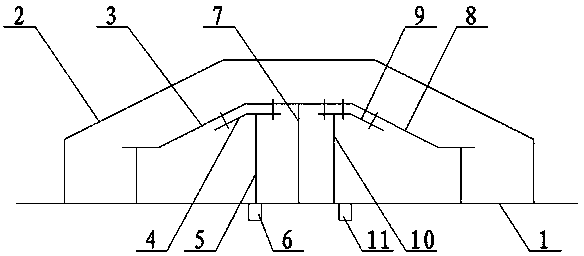
[0014] figure 1 As shown, a coupled feeding inverted F antenna includes a base plate 1, an insulating cover 2, a left radiator 3, a coupling feeding sheet 4, a feeding rod 5, a feeding interface 6, a grounding column 7, a right radiator 8, a coupling Ground sheet 9, ground rod 10 and ground interface 11. The left and right radiators are arranged opposite to each other symmetrically and are sealed and packaged on the base plate 1 through an insulating cover 2. The left radiator includes a left radiator 3, a coupling feeding sheet 4, a feeding rod 5 and a grounding column 7. The outer radiator of the left radiator 3 The side is insulated and supported on the bottom plate 1, and the coupling feed sheet 4 supported by the feed rod 5 is provided under the middle part of the left radiator 3. The coupling feed sheet and the left radiator are coupled in parallel, and the feed ...


PUM


Abstract

The invention relates to a coupled feeding inverted F antenna which comprises a bottom plate, an insulating cover and an antenna body. The antenna body is sealed and packed on the bottom plate through the insulating cover. The antenna body comprises a left radiating body and a right radiating body, wherein the left radiating body and the right radiating body are oppositely and symmetrically arranged. The outer lateral edge of a left radiator is supported by the bottom plate in an insulating mode, a coupled feeding piece supported by a feeding rod is arranged under the middle of the left radiator, the coupled feeding piece and the left radiator are arranged and coupled in parallel, the feeding rod is connected with a feeding opening under the bottom plate, and the inner lateral edge of the left radiator is supported by the bottom plate through a ground connection column and penetrates through the bottom plate to be outwards connected with the ground. The outer lateral edge of a right radiator is supported by the bottom plate in an insulating mode, a coupled ground connection piece supported by a ground connection rod is arranged under the middle of the right radiator, the coupled ground connection piece and the right radiating body are coupled and arranged in parallel, the ground connection rod is connected with a ground connection opening under the bottom plate, and the inner lateral edge of the right radiator is supported by the floor through the ground connection column.

Description

technical field [0001] The invention relates to an inverted-F antenna, in particular to a coupled-feed inverted-F antenna. Background technique [0002] With the development of wireless local area network communication technology, the requirements for its built-in antenna are getting higher and higher, and miniaturized antennas with small volume and light weight are required. Since the inverted-F antenna has the advantage of miniaturization, it is widely used in various wireless local area network devices. However, the inverted F antenna has strong directivity in wireless coverage, and the horizontal coverage is uneven, resulting in poor omnidirectional performance of the antenna, which cannot meet the higher requirements of the antenna. Contents of the invention [0003] In view of the poor omnidirectional performance of the inverted F antenna in the prior art, the present invention provides a coupling-fed inverted F antenna with a simple structure, which can effectively...

Claims


Application Information

Patent Timeline
Patent Type & Authority Applications(China)
IPC IPC(8): H01Q1/36H01Q1/48H01Q1/50
Inventor 周红兵王丽王鸿来杨志
Owner TAIXING DONGSHENG ELECTRONICS EQUIP FACTORY
Learn More