
On-site large-scale direct shear test device for detecting shear strength of cohesive soil

A technology of shear strength and test equipment, which is applied in the direction of applying stable shear force to test the strength of materials, can solve the problems of not being able to fully reflect the real strength of cohesive soil, unable to test samples, and limited applicable occasions, etc., to achieve The effects of stable force application, small footprint, and improved safety

Inactive Publication Date: 2014-11-12
CHANGJIANG SURVEY PLANNING DESIGN & RES +1
View PDF6 Cites 2 Cited by
  • Summary
  • Abstract
  • Description
  • Claims
  • Application Information

AI Technical Summary

Problems solved by technology

[0003] Due to the limitation of the sample selection in the current indoor test, there are many factors affected by man-made and weather, the samples are mostly soil blocks, and the volume is small, easy to disturb, while the vertical shear test device used in the existing large Stacking not only takes up a lot of space, but also is prone to accidents. Therefore, it cannot fully reflect the real strength of cohesive soil
At the same time, the existing large-scale direct shear test device can only detect samples on the horizontal ground but cannot detect samples on slopes, and the applicable occasions are limited

Method used


Image

  • On-site large-scale direct shear test device for detecting shear strength of cohesive soil
  • On-site large-scale direct shear test device for detecting shear strength of cohesive soil
  • On-site large-scale direct shear test device for detecting shear strength of cohesive soil

Examples


Embodiment Construction

[0018] The present invention will be described in further detail below in conjunction with the accompanying drawings and embodiments, but these embodiments should not be construed as limiting the present invention.

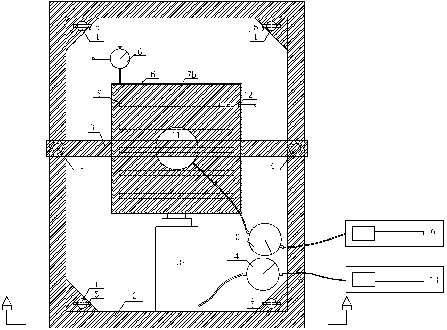
[0019] see Figure 1 to Figure 2 , the on-site large-scale direct shear test device for detecting the shear strength of cohesive soil in the present invention includes a ground anchor 1, a load-bearing frame seat 2, a transverse beam 3, a bolt 4, a stud 5, a sample box 6, a lower plate 7a, an upper Plate 7b, roller 8, vertical hydraulic pump 9, vertical pressure gauge 10, vertical force measuring jack 11, vertical displacement indicator 12, lateral hydraulic pump 13, lateral pressure gauge 14, lateral force measuring jack 15. Lateral displacement indicator table 16 and fixed bracket 17.

[0020] The sample box 6 is used to place the cohesive soil sample to control the force of the sample. The length, width and height of the sample box 6 are respectively 40cm×40cm...


PUM


Abstract

The invention discloses an on-site large-scale direct shear test device for detecting the shear strength of cohesive soil. The on-site large-scale direct shear test device comprises a sample box, a lateral force test jack and a lateral displacement dial indicator, and further comprises a force bearing framework base. The sample box is used for containing cohesive soil samples and controlling stress on the samples. The lateral force test jack is connected with a lateral hydraulic pump through a lateral pressure gauge. The lateral displacement dial indicator is anchored through a fixing support. The force bearing framework base is anchored through a ground anchor and located on the outer side of the sample box. The inner side wall of the force bearing framework base and the outer side wall of the sample box abut against the two ends of the lateral force test jack respectively. The lateral displacement dial indicator is connected with the outer side wall of the sample box. The detection direction of the lateral displacement dial indicator is parallel to the arrangement direction of the lateral force test jack. The on-site large-scale direct shear test device has the advantages that the structure is simple, installation is easy, data of the shear strength of the cohesive soil can be obtained truly and effectively, and the on-site direct shear test device is suitable for various places and can be widely applied to the technical field of cohesive soil detection.

Description

technical field [0001] The invention relates to the technical field of cohesive soil detection, in particular to an on-site large-scale direct shear test device for detecting the shear strength of cohesive soil. Background technique [0002] In engineering geological survey and engineering construction, in order to obtain the shear strength value of cohesive soil, it is necessary to use instruments to test it. [0003] Due to the limitation of the sample selection in the current indoor test, there are many factors affected by man-made and weather, the samples are mostly soil blocks, and the volume is small, easy to disturb, while the vertical shear test device used in the existing large Stacking not only takes up a lot of space, but also is prone to accidents. Therefore, it cannot fully reflect the real strength of cohesive soil. At the same time, the existing large-scale direct shear test device can only detect samples on the horizontal ground but cannot detect samples on ...

Claims


Application Information

Patent Timeline
Patent Type & Authority Applications(China)
IPC IPC(8): G01N3/24
Inventor 阳云华赵旻强鲁斌赵鑫朱瑛洁张良平麻斌耿军民
Owner CHANGJIANG SURVEY PLANNING DESIGN & RES
Learn More