
Elastic rail type automatic pipeline outer wall welding mechanism

A technology for elastic rails and outer walls of pipes, applied in welding equipment, auxiliary welding equipment, welding/cutting auxiliary equipment, etc., can solve the problems of poor overall forming quality, high physical strength and technical requirements of welders, oil and natural gas leakage, etc. Problems, to achieve the effect of light weight, easy operation, stable and reliable operation

Inactive Publication Date: 2014-11-12
HARBIN ENG UNIV
View PDF5 Cites 56 Cited by
  • Summary
  • Abstract
  • Description
  • Claims
  • Application Information

AI Technical Summary

Problems solved by technology

During the process of the pipeline fulfilling its mission, due to the long-term oil and gas corrosion and erosion and the influence of the external environment on the pipeline, the pipe wall becomes thinner and thinner, so that it cannot work normally, and even oil and natural gas leakage occurs, which not only wastes There are a lot of natural resources, and it causes great pollution to the nearby environment. Therefore, the development of a mechanism that can quickly increase the thickness of the pipe wall can not only greatly improve the repair speed of the thinner wall thickness, but also reduce the labor of workers. Labor-intensive, increases the service life of the pipeline, and has high research value
[0003] The domestic research on pipeline welding started relatively late, and the welding of large-diameter pipelines is less, mainly the welding of planar structures. The flexible orbital welding trolley developed by Harbin Keneng Deposition Company has a low degree of automation. The adjustment of the block requires the operator to support it at hand during the work process, which requires high physical strength and technical requirements for the welder, and cannot guarantee the overall forming quality.

Method used


Image

  • Elastic rail type automatic pipeline outer wall welding mechanism
  • Elastic rail type automatic pipeline outer wall welding mechanism
  • Elastic rail type automatic pipeline outer wall welding mechanism

Examples


Embodiment Construction

[0020] The present invention is described in more detail below in conjunction with accompanying drawing example:

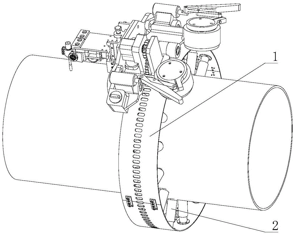
[0021] figure 1 Among them, the elastic track-type pipeline outer wall automatic welding mechanism and the elastic track mechanism 1 are assembled to form an all-position pipeline welding robot, which is applied to the outer wall welding of circular straight pipelines. The elastic track type pipe outer wall automatic welding mechanism mainly has four control degrees of freedom in the work, which are 3600 degrees of freedom to rotate along the circular track, the radial movement mechanism to move the degree of freedom along the diameter of the pipe, and the axial movement mechanism to move along the parallel The degree of freedom of reciprocating movement in the axial direction of the pipe, and the degree of freedom of the circular reciprocating swing of the welding torch.

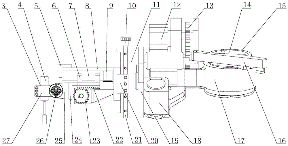
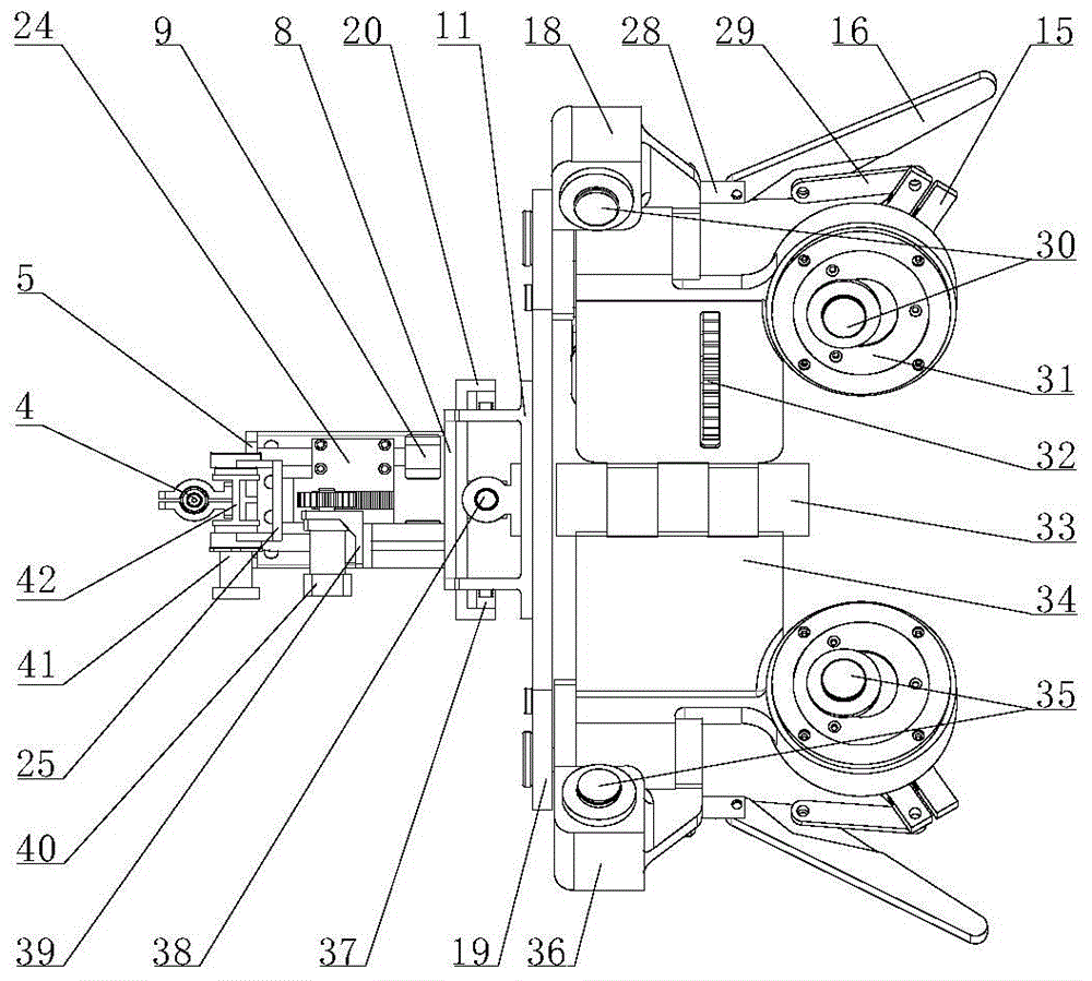
[0022] combine Figure 2-5 , the present invention includes a circumferential drive motor...


PUM


Abstract

The invention provides an elastic rail type automatic pipeline outer wall welding mechanism. Two cam bases are connected through a pin shaft, the two cam bases are adjustable in angle and suitable for different pipe diameters, and the two cam bases are fixed to a rail through cam locking mechanisms. An angle adjusting plate, wheel bases and cam bases can jointly form a basic framework of a welding trolley. The welding trolley are driven by gears and can do uniform circular motion around the elastic rail. A welding gun radial moving mechanism is arranged on the angle adjusting plate and is manually adjusted, a welding gun axial moving mechanism is connected to the radial moving mechanism, an axial moving driving motor can drive a rack to move to achieve axial welding gun movement, a welding gun swinging mechanism is arranged at the front end of a rack supporting seat, and a welding gun is directly driven by a stepping motor to swing around the welding joint center in a cycling and reciprocating mode. The elastic rail type automatic pipeline outer wall welding mechanism has the advantages of achieving miniaturization and modularization and being light in weight, even in weight distribution, economical and practical, simple to control, stable in operation and conveniently matched with various walking mechanisms of pipeline outer wall welding machines.

Description

technical field [0001] The invention relates to a pipeline welding device. Background technique [0002] Pipelines are now widely used in long-distance transportation projects of natural gas and oil. With the gradual deepening and expansion of my country's West-East Gas Pipeline Project, higher and newer requirements are constantly being put forward for the transportation capacity and service life of pipelines. This meets the demand for oil and natural gas in the developed eastern regions. During the process of the pipeline fulfilling its mission, due to the long-term oil and gas corrosion and erosion and the influence of the external environment on the pipeline, the pipe wall becomes thinner and thinner, so that it cannot work normally, and even oil and natural gas leakage occurs, which not only wastes There are a lot of natural resources, and it causes great pollution to the nearby environment. Therefore, the development of a mechanism that can quickly increase the thickne...

Claims


Application Information

Patent Timeline
IPC IPC(8): B23K37/02
CPCB23K37/0217B23K37/027B23K37/0294
Inventor 马洪文杨柳王俊明赵志明
Owner HARBIN ENG UNIV
Learn More