
Automatic liquid-stopping dripping funnel

A dripping funnel and stop liquid technology, applied in the field of medical devices, can solve problems such as hidden quality problems, buoy blockage, quality problems, etc., and achieve the effects of avoiding liquid medicine waste, convenient use, and simple structure

Active Publication Date: 2014-11-12
SHANDONG WEIGAO GROUP MEDICAL POLYMER
View PDF9 Cites 3 Cited by
  • Summary
  • Abstract
  • Description
  • Claims
  • Application Information

AI Technical Summary

Problems solved by technology

The main defects of the traditional buoy drop bucket are: (1) The liquid stop effect is greatly affected by the composition and purity of the liquid medicine. If there are any impurities or particles, the plastic buoy cannot fit the infusion tube, thus losing the automatic stop liquid (2) The requirements for the tightness of the buoy accessories and the interface of the infusion tube are very high, so the production and processing methods of the above two accessories are very strict, such as the precision of the mold, the selection of raw materials, and the production process. A large amount of verification and control is required for the control of the plastic accessories and whether the plastic parts are deformed after sterilization. A little carelessness will directly cause the product to lose the automatic liquid stop function and cause quality problems; (3) The buoy is set under the dripping funnel. After the liquid level drops to a certain level, the buoy blocks the liquid outlet of the dripping funnel to achieve the purpose of stopping the liquid. In this way, the liquid level usually drops to the lower 1 / 3 of the dripping funnel cavity or even near the liquid outlet of the dripping funnel

Method used


Image

  • Automatic liquid-stopping dripping funnel
  • Automatic liquid-stopping dripping funnel

Examples


Embodiment Construction

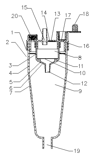
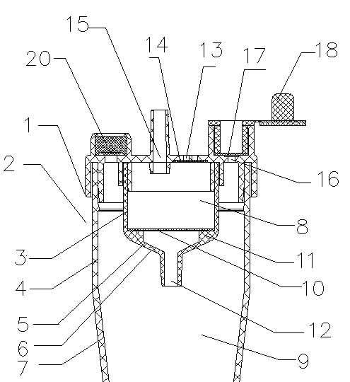
[0014] Such as figure 1 with figure 2 As shown, a kind of automatic liquid-stop dripping funnel comprises dripping funnel cover 1 and dripping funnel body 2, and dripping funnel cover 1 is arranged on the top of dripping funnel body 2, and described dripping funnel body 2 is made up of inner dripping funnel 3, outer dripping funnel 4 components, the inner wall 5 of the inner dripping funnel is combined with the dripping funnel cover 1 to form the inner dripping funnel chamber 8, the top of the inner dripping funnel chamber 8 is equipped with a vent hole 13, and the dripping funnel cover 1 on the upper part of the inner dripping funnel chamber 8 is provided with a dripping funnel The liquid inlet pipe 15, the upper part of the inner dripping funnel liquid outlet 12 at the bottom of the inner dripping funnel 3 is provided with a liquid stop filter membrane 10; the outer dripping funnel inner wall 7, the dripping funnel cover 1 and the inner dripping funnel outer wall 6 are comb...


PUM


Abstract

The invention discloses an automatic liquid-stopping dripping funnel. The dripping funnel comprises a dripping funnel cover and a dripping funnel body, wherein the dripping funnel cover is arranged at the top of the dripping funnel body. The dripping funnel is characterized in that the dripping funnel body consists of an inner dripping funnel and an outer dripping funnel; the inner wall of the inner dripping funnel and the dripping funnel cover are combined into an inner dripping funnel cavity; a vent hole is matched with the top of the inner dripping funnel cavity; a dripping funnel liquid inlet pipe is arranged on the dripping funnel cover at the upper part of the inner dripping funnel cavity; a liquid-stopping filter membrane is arranged at the upper part of an inner dripping funnel liquid outlet at the bottom end of the inner dripping funnel; the inner wall of the outer dripping funnel, the dripping funnel cover and the outer wall of the inner dripping funnel are combined into an outer dripping funnel cavity; an air inlet capable of being opened and closed is matched with the outer dripping funnel cavity; a dripping funnel liquid outlet is arranged at the lower part of the outer dripping funnel cavity. The dripping funnel is reasonable in structure, reliable in liquid stopping effect, simple in machining technology and convenient to operate.

Description

technical field [0001] The invention belongs to the field of medical equipment, and relates to a medical equipment for intravenous transfusion for clinical patients, in particular to an automatic drip stopper. technical background [0002] At present, a disposable infusion set is a commonly used medical device, which generally includes a bottle stopper piercer, a drip funnel, a flow regulator, a liquid medicine filter, and an intravenous infusion needle, which are connected in series by an infusion catheter. The medicinal liquid flows in through the bottle stopper piercer, flows into the infusion catheter through the outlet of the dropping funnel, and enters the human body through the medicinal liquid filter and the intravenous infusion needle. In the clinical infusion process, the accompanying person needs to pay close attention to the liquid level of the liquid medicine, otherwise the phenomenon that the liquid medicine in the infusion bottle has been infused and the infus...

Claims


Application Information

Patent Timeline
IPC IPC(8): A61M5/38
Inventor 马之骁田学飞
Owner SHANDONG WEIGAO GROUP MEDICAL POLYMER
Learn More