
Movable electroplate hanger

A technology of electroplating hangers and fixtures, which is applied in the direction of electrolysis process and electrolysis components to achieve the effect of fast movement and convenient lateral movement

Inactive Publication Date: 2014-11-05
周元忠
View PDF0 Cites 3 Cited by
  • Summary
  • Abstract
  • Description
  • Claims
  • Application Information

AI Technical Summary

Problems solved by technology

In the process of electroplating, there will be situations where the outer surface of a metal needs to be electroplated with several layers at the same time, and it will be difficult to move

Method used


Image

  • Movable electroplate hanger

Examples


Embodiment 1

[0015] Embodiment 1: A movable electroplating hanger

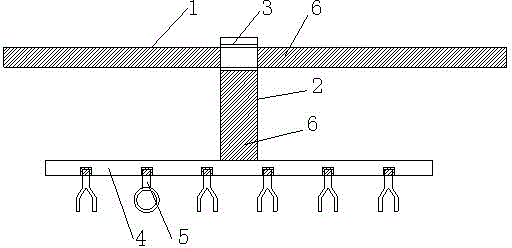
[0016] Such as figure 1 As shown, a movable electroplating hanger of the present invention includes a cross bar 1 and a fixed bar 2. The head of the fixed bar 2 is provided with a connecting hole 3 that can movably connect the fixed bar 2 and the cross bar 1. The fixed bar The bottom of 2 is connected to the hanging rod group, and the hanging rod group is composed of no less than two main rods 4 parallel to each other. The lower end of the main rod 4 is provided with a clamp 5, which is open and closed. It is formed by placing, the clamp 5 and the main rod 4 are screwed together, and the horizontal rod 1 and the fixed rod 2 are provided with an insulating sleeve 6 outside.

[0017] The horizontal bar 1 and the fixed bar 2 are movably connected together through the connecting hole 3, which facilitates the lateral movement of the fixed bar 2, and can quickly realize the movement of the hanging bar during the electroplating...


PUM


Abstract

The invention relates to an electroplate hanger, and especially relates to a movable electroplate hanger. The movable electroplate hanger comprises a cross rod and a fixed rod; the head part of the fixed rod is provided with a connection hole, which can movably connect the fixed rod and the cross rod; the bottom part of the fixed rod is connected to a hanging rod set, which is composed of at least two main rods parallel to each other; the lower end of each main rod is provided with a clamping device, the clamping devices are divided into two types: an open-mouth type and a closed-mouth type, and the two types of clamping devices are staggeredly arranged. The cross rod and the fixed rod are moveably connected together through the connection hole, and thus the fixed rod can freely move in the horizontal direction, so during the electroplating process, the hanger can be quickly moved. Furthermore, the two types of clamping devices arranged on the lower ends of the main rods are staggeredly arranged, so a proper hanging mode can be selected according to the size of a product to be electroplated.

Description

Technical field [0001] The present invention involves an electroplating hanging utensils, especially a moving electroplating hanging utensil. Background technique [0002] Electroplating is the process of plating other metals and alloy thin layers on the surface of certain metals on the surface of certain metals. Using electrolytic effects can attach a layer of metal membrane to the surface of metal or other materials to prevent duplex and abrasion resistance.Conductivity, reflectivity and improvement of beauty.In the process of electroplating, a metal exterior will appear at the same time that need to be plated at the same time, and it will cause difficulties when moving.Therefore, a new technical solution should be provided to solve the above problems. Invention content [0003] The purpose of the present invention is to provide a convenient improving pedaling bed for the above deficiencies. [0004] To achieve the above goals, the technical solution adopted by the present in...

Claims


Application Information

Patent Timeline
Patent Type & Authority Applications(China)
IPC IPC(8): C25D17/08
Inventor 周元忠
Owner 周元忠
Learn More