
An optical lens automatic dust removal device

An optical lens, automatic dust removal technology, applied in optics, optical components, chemical instruments and methods, etc., can solve the problems of high labor intensity of workers, high equipment cost, affecting imaging quality, etc., to improve market competitiveness and reduce labor intensity. , The effect of improving cleaning efficiency

Active Publication Date: 2016-02-17
HUIZHOU DESAY AUTOMATION TECH
View PDF7 Cites 0 Cited by
  • Summary
  • Abstract
  • Description
  • Claims
  • Application Information

AI Technical Summary

Problems solved by technology

In the actual production process, after the optical lens is assembled, tiny dust particles usually adhere to the outer periphery, reference plane and sky surface of the optical lens. If the dust particles are not cleaned in time, the image quality will be seriously affected after assembly. , or affect the implementation and effect of the algorithm
[0003] At present, there are dust collectors on the market to remove dust particles from optical lenses, but the efficiency is very low. It takes about 10 minutes for every 100 lens barrels, and the product is very single, and the model cannot be replaced. The cost of equipment is very high, and the labor intensity of workers It is also very large, and the product quality is difficult to guarantee, which reduces the market competitiveness of the enterprise

Method used


Image

  • An optical lens automatic dust removal device
  • An optical lens automatic dust removal device
  • An optical lens automatic dust removal device

Examples


Embodiment Construction

[0020] In order to facilitate the understanding of those skilled in the art, the present invention will be further described in detail below with reference to the accompanying drawings and embodiments.

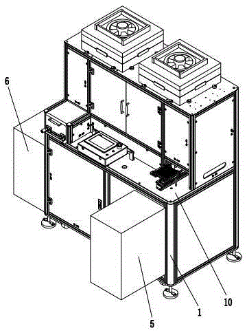
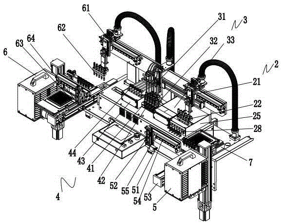
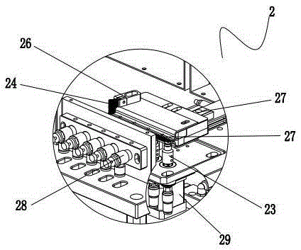
[0021] As attached Figure 1~4 As shown, an optical lens automatic dust removal equipment includes a frame 1 and a workbench 10 set on the frame 1. The workbench is sequentially provided with an outer wall cleaning mechanism 2, a reference surface cleaning mechanism 3, and a sky surface cleaning mechanism 4. The outer side wall cleaning mechanism 2 cleans the outer side wall of the optical lens, that is, the outer periphery of the optical lens, the reference surface cleaning mechanism 3 cleans the reference surface of the optical lens, that is, the bottom surface of the optical lens, and the top surface cleaning mechanism 4 cleans the top surface of the optical lens, that is, the optical lens The top surface, the outer wall cleaning mechanism 2, the reference surface cleaning mec...


PUM


Abstract

An automatic dust removal device for an optical lens comprises a rack and a workbench arranged on the rack, wherein an outer side wall cleaning mechanism used for cleaning the outer side wall of the optical lens, a reference surface cleaning mechanism used for cleaning the reference surface of the optical lens and a top surface cleaning mechanism used for cleaning the top surface of the optical lens are sequentially arranged on the workbench, and the mechanisms are connected with a master control circuit and controlled by the master control circuit. The automatic dust removal device for the optical lens is reasonable in structural design, motion of the mechanisms are controlled in an electrical control mode, cleaning efficiency and cleaning quality of products are improved, labor intensity of workers is greatly reduced, production cost is greatly saved, the device is especially suitable for the requirement for cleaning optical lenses in a batch mode, and market competitiveness of enterprises is improved. The dust removal device can meet the requirement of optical lenses with different sizes for cleaning and dust removal through replacement of a lower suction head and a lower clamping assembly and can be used in multiple ways, functional waste is avoided to the greatest extent, and cost is saved. The cleaning speed of the dust removal device can also be controlled, and according to the cleaning efficiency, 2500 optical lenses can be cleaned per hour.

Description

Technical field [0001] The invention relates to a dust removal equipment, in particular to an optical lens automatic dust removal equipment. Background technique [0002] Optical lens is a kind of precision parts with very wide application. In the actual production process, after the optical lens is assembled, there are usually tiny dust particles attached to the outer periphery, reference surface and sky surface of the optical lens. If the dust particles are not removed in time, the quality of the image will be seriously affected after assembly. , Or affect the realization and effect of the algorithm. [0003] At present, there are dust collectors on the market that remove dust particles from optical lenses, but the efficiency is very low. It takes about 10 minutes for every 100 lens barrels. The product is very single and cannot be replaced. The equipment cost is very high and the labor intensity of workers It is also very large, and the product quality is difficult to guarante...

Claims


Application Information

Patent Timeline
Patent Type & Authority Patents(China)
IPC IPC(8): B08B11/00B08B11/02G02B27/00
CPCB08B11/00B08B11/02G02B27/0006B08B5/023B08B11/04
Inventor 徐巍
Owner HUIZHOU DESAY AUTOMATION TECH
Learn More