Crank case oil-filter mechanism

A technology of oil filter and crankcase, applied in the field of crankcase components, to achieve the effect of overcoming complex structure, simple structure, and quick disassembly and assembly

Inactive Publication Date: 2014-11-05
XUZHOU KAILONG MINING SCI & TECH DEV
View PDF0 Cites 0 Cited by
  • Summary
  • Abstract
  • Description
  • Claims
  • Application Information

AI Technical Summary

Problems solved by technology

[0005] Beneficial effect of the present invention: because the present invention has adopted above-mentioned scheme, oil filter is installed on one side of crankcase, and oil filter connects air inlet, and air inlet connects cylinder, then by input pipe and output pipe and crankcase Butt joint, so that the entire crankcase oil filter mechanism has the advantages of simple structure, quick disassembly and assembly, convenient maintenance, and the oil filter is not easy to leak oil, which effectively overcomes the complex structure, disassembly and assembly of the existing crankcase oil filter mechanism. Troublesome, difficult to maintain, serious oil filter defects

Method used


Image

  • Crank case oil-filter mechanism

Examples


Embodiment Construction

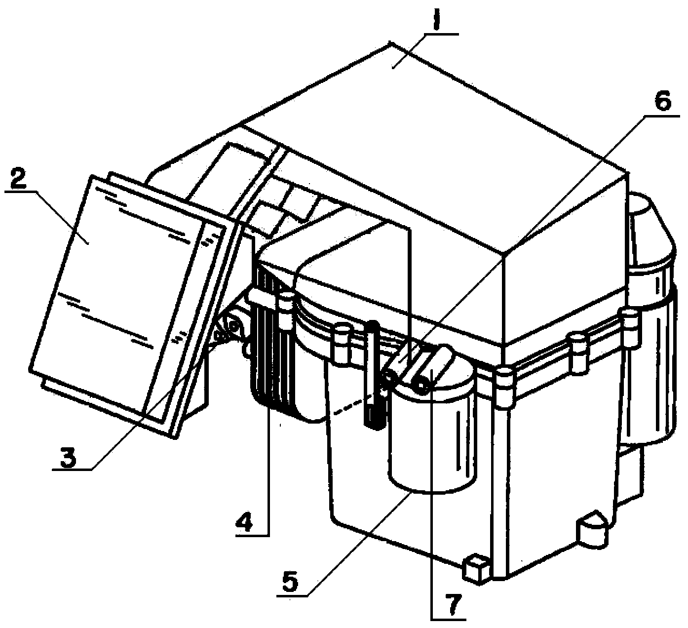
[0009] The oil filter mechanism has a crankcase (1), and a filter (2) is arranged on one side of the crankcase (1), and an air inlet (3) is connected to the filter (2). A cylinder (4) and an oil filter (5) are arranged on one side of the oil filter (5). An input pipe (6) and an output pipe (7) are arranged on the oil filter (5). The oil filter (5) passes through the input pipe ( 6) and the output pipe (7) are connected in the inner cavity of the cylinder (4).


PUM


Abstract

A crank case oil-filter mechanism. A filter is disposed at one side of a crank case. A gas inlet is connected to the filter. A cylinder and an oil filter are arranged at one side of the gas inlet. An input pipe and an output pipe are disposed on the oil filter. The oil filter is connected to an internal chamber of the cylinder through the input pipe and the output pipe. The crank case oil-filter mechanism is simple in structure, is quick to disassemble and is convenient to maintain. Oil in the oil filter is not liable to leak. Defects that a conventional crank case oil-filter mechanism is complex in structure, is inconvenient to disassemble and is difficult to maintain and the oil in the oil filter is liable to leak seriously are effectively overcome.

Description

technical field [0001] The invention relates to an oil filter mechanism, in particular to a crankcase oil filter mechanism, which belongs to the technical field of crankcase components. Background technique [0002] The crankcase oil filter mechanism is an important component of the crankcase mechanism. In the existing crankcase oil filter mechanism, the boundary line of the crankcase is located between the side wall and the bottom surface of the crankcase, which is usually lower than the oil sump plane. On the lower side, the crankcase oil filter structure of this structure has the defects of complicated structure, troublesome disassembly and assembly, difficult maintenance, and serious oil leakage of the oil filter. Contents of the invention [0003] The purpose of the present invention is to provide a crankcase oil filter mechanism with simple structure, fast disassembly and assembly, convenient maintenance, and the oil filter is not easy to leak oil, so as to overcome ...

Claims


Application Information

Patent Timeline
Patent Type & Authority Applications(China)
IPC IPC(8): B01D35/02
Inventor 张胜凯
Owner XUZHOU KAILONG MINING SCI & TECH DEV
Why Eureka
Try Eureka