
Subregion local variable-density non-equidistant dual mesh division method for complex mountainous region

A technology of grid division and grid refinement, which is applied in seismic signal processing, test sample preparation, instruments, etc., to achieve the effect of increasing the depth sampling rate

Inactive Publication Date: 2014-10-29
JILIN UNIV
View PDF1 Cites 9 Cited by
  • Summary
  • Abstract
  • Description
  • Claims
  • Application Information

AI Technical Summary

Problems solved by technology

[0009] The purpose of the present invention is to provide a dual grid with variable local density and unequal distance for complex mountainous areas to address the defects of the above-mentioned existing uniform and single ladder grid, unequal grid, and curved grid. Subdivision method

Method used


Image

  • Subregion local variable-density non-equidistant dual mesh division method for complex mountainous region
  • Subregion local variable-density non-equidistant dual mesh division method for complex mountainous region
  • Subregion local variable-density non-equidistant dual mesh division method for complex mountainous region

Examples


Embodiment 1

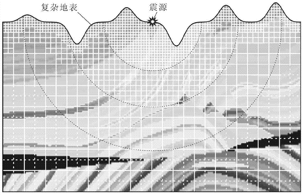
[0031] Such as figure 2As shown in , a complex surface Marmousi model is introduced to the classic Marmousi model after adding surface correction, and the surface fluctuation of this model is relatively severe. When using the grid subdivision technology of the present invention to subdivide it, set the grid spacing of the larger square coarse grid used in step b as h. When performing exponential encryption on the grid near the surface, the maximum index factor is n=4, that is, the distance between the nearest grid to the surface is h / 16, and each exponential encryption factor (respectively n=4, 3, 2) corresponds to The range of the grid densification area starts from the surface and extends downward successively for no more than 1.0h, 1.5h, and 2.0h. When performing exponential refinement on the grid near the seismic source, the maximum exponential factor is n=4, that is, the distance between the grids closest to the seismic source is h / 16, and each exponential refinement fa...

Embodiment 2

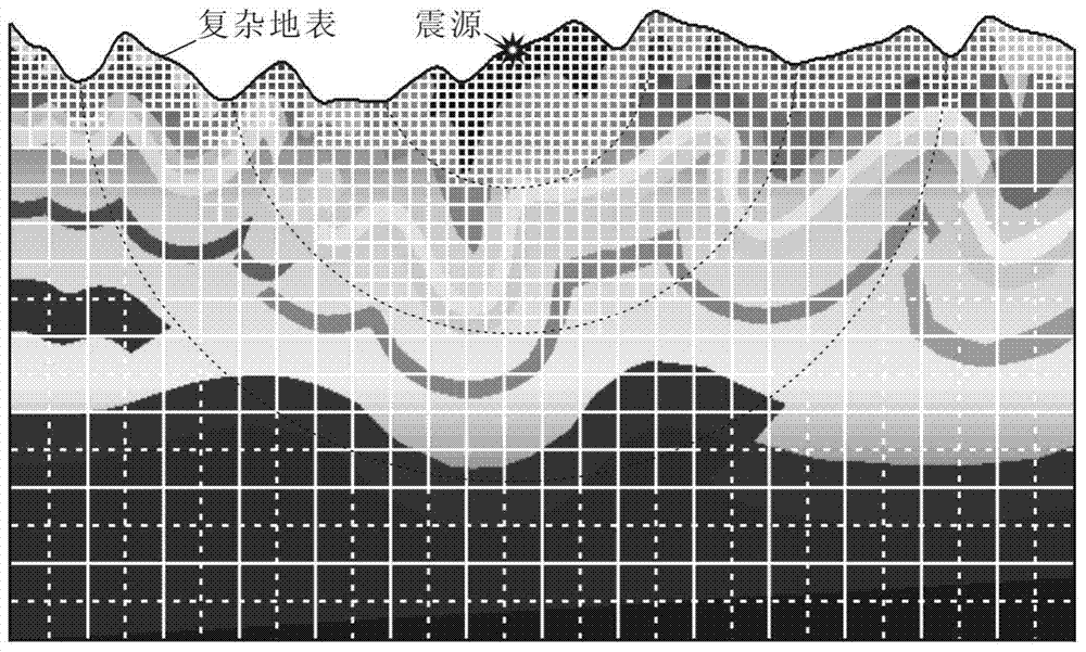
[0033] Such as image 3 As shown, the model is the classic SEG undulating surface Foothill model, and the surface elevation changes in some areas of this model are relatively drastic. Also, when it is subdivided by the grid subdivision technology of the present invention, the grid spacing of the larger square coarse grid used in step b is set to be h. When performing exponential encryption on the grid near the surface, the maximum index factor is n=4, that is, the distance between the nearest grid to the surface is h / 16, and each exponential encryption factor (respectively n=4, 3, 2) corresponds to The range of the grid densification area starts from the surface and extends downward successively for no more than 1.0h, 1.5h, and 2.0h. When performing exponential refinement on the grid near the seismic source, the maximum exponential factor is n=4, that is, the distance between the grids closest to the seismic source is h / 16, and each exponential refinement factor (respectively...


PUM


Abstract

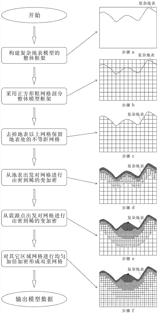
The invention relates to a subregion local variable-density non-equidistant dual mesh division method for a complex mountainous region. The method comprises the steps that an overall model framework of the complex mountainous region is established according to the earth surface elevation and the calculated region range, the whole model framework is divided through square coarse meshes in sequence, a complex earth surface nearby region is divided through variable-density densified non-equidistant meshes, a seismic origin nearby region is divided through variable-density densified meshes, and other regions are divided through dual uniformly-multiplied densified meshes. By means of the meshes, the complex earth surface morphology and the distribution conditions of complex media nearby the earth surface can be depicted accurately and subtly, the boundary conditions nearby the complex earth surface can be achieved accurately and stably, the problem of a large error nearby a source point can be solved on the premise of not substantially increasing the calculated amount, the calculating efficiency can be improved substantially on the premise of guaranteeing the calculating accuracy, and spending of too much mesh generation cost, an extra storage space and extra calculated amount are not needed.

Description

technical field [0001] The invention relates to a grid subdivision method for complex medium models in technologies such as seismic wave numerical simulation and data processing in the field of geophysics, especially a fine grid subdivision method for complex mountain models. Background technique [0002] Complex mountainous geological conditions often bring many thorny problems to technologies such as seismic wave numerical simulation and data processing in complex mountainous areas. The meshing technology for complex mountain models is a basic and key technology that affects the accuracy, efficiency, and stability of seismic wave numerical simulation and data processing technologies under complex mountain conditions. [0003] At present, for the grid division of complex mountain models, uniform and single stepped grids, unequal grids, and curved grids are usually used. In the important technical links such as the accurate description of the complex surface shape of the co...

Claims


Application Information

Patent Timeline
IPC IPC(8): G06F19/00G01V1/28G01N1/30
Inventor 孙章庆孙建国
Owner JILIN UNIV
Learn More