
Device for positioning a rotor of a gas turbine and gas turbine

A technology for gas turbines and rotors, applied in the directions of blade support elements, engine elements, machines/engines, etc., to solve problems such as difficulty in controlling motion and oil not being an actuating medium

Active Publication Date: 2016-09-28
ANSALDO ENERGIA SWITZERLAND AG
View PDF11 Cites 0 Cited by
  • Summary
  • Abstract
  • Description
  • Claims
  • Application Information

AI Technical Summary

Problems solved by technology

The problem with this type of device is that it is difficult to control its movement since it is actuated by oil
Also, oil is not the preferred activating medium to use since cleaning has to be done on a routine basis, which thus requires time and additional cost

Method used


Image

  • Device for positioning a rotor of a gas turbine and gas turbine

Examples


Embodiment Construction

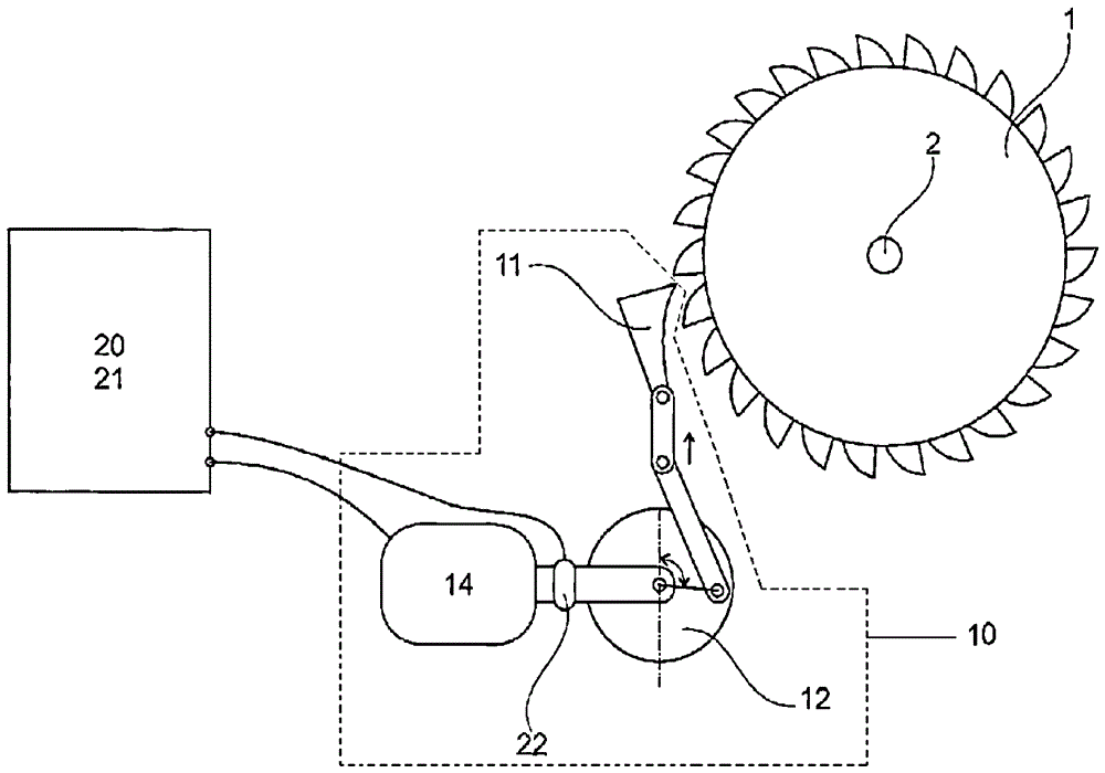
[0017] The invention relates to a device for positioning a gas turbine rotor 2 in a precise manner. The device comprises a piston rod 11 which linearly moves its ratchet 1 which moves the gas turbine rotor 2 . The drive mechanism 10 comprises an eccentric 12 and a drive device (preferably a synchronous motor 14). The piston rod 11 is moved by an eccentric 12 connected to a synchronous motor 14 .

[0018] The synchronous motor 14 of the drive mechanism 10 allows precise control of its angular position by means of an incremental counter.

[0019] The frequency converter 21 can vary the rotational speed of the synchronous motor 14, which determines the speed and position of the piston rod 11, and the output torque of the synchronous motor, which allows the definition of the applied linear force.

[0020] The conversion of the triangular trajectory from the rotational movement of the synchronous motor 14 to the linear movement of the piston rod 11 is performed by the motion cont...


PUM


Abstract

The invention relates to a device for positioning a rotor of a gas turbine and to a gas turbine. In particular, it relates to a device (10) for positioning a gas turbine rotor (2), which device (10) linearly actuates a piston rod (11) which by its end actuates a ratchet gear (1), the ratchet (1) moves the gas turbine rotor (2), the device (10) includes an eccentric (12) and a synchronous motor (14), so that the piston rod (11) is connected to the synchronous motor ( 14) the eccentric wheel (12) to move. The device (10) also includes an incremental counter (22) that controls the angular position of the synchronous motor (14).

Description

technical field [0001] The present invention relates to electromechanical devices for positioning gas turbine rotors in a precise manner. Background technique [0002] During the useful life of a gas turbine, maintenance operations are required for ensuring the correct function of the turbine itself. During these periodic operations, controls and inspections are completed and damaged or worn parts or components are replaced. [0003] The most worn parts of a turbine are the turbine blades, since they are subjected to mechanical stress at high temperatures and thermal corrosion due to the hot gases with which the turbine operates. Thus, periodic inspection of turbine blades is required to control their integrity and functionality. During scheduled maintenance operations, in order to be able to inspect the turbine blades, it is often necessary to rotate the turbine blades, which is done by rotating the entire turbine rotor. This is done in particular in the case of borescop...

Claims


Application Information

Patent Timeline
Patent Type & Authority Patents(China)
IPC IPC(8): F01D25/34F01D5/02
CPCF01D25/36Y10T74/18056
Inventor F.斯塔伊里A.哈尔姆斯D.马特斯
Owner ANSALDO ENERGIA SWITZERLAND AG
Learn More