
A Direct Digital Frequency Synthesizer

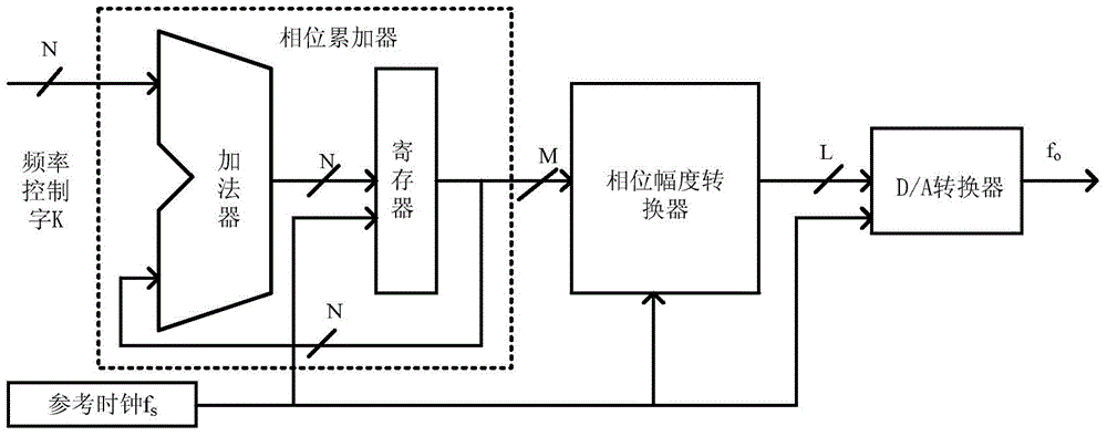
A digital frequency synthesis, direct technology, applied in the direction of automatic power control, electrical components, etc., can solve the problems of direct digital frequency synthesizer power consumption increase, etc., to reduce the working clock, reduce power consumption, improve conversion speed and accuracy Effect

Active Publication Date: 2017-03-15
58TH RES INST OF CETC
View PDF2 Cites 0 Cited by
  • Summary
  • Abstract
  • Description
  • Claims
  • Application Information

AI Technical Summary

Problems solved by technology

Direct Digital Synthesizer Power Consumption Increases As Frequency Increases

Method used


Image

  • A Direct Digital Frequency Synthesizer
  • A Direct Digital Frequency Synthesizer
  • A Direct Digital Frequency Synthesizer

Examples


Embodiment 1

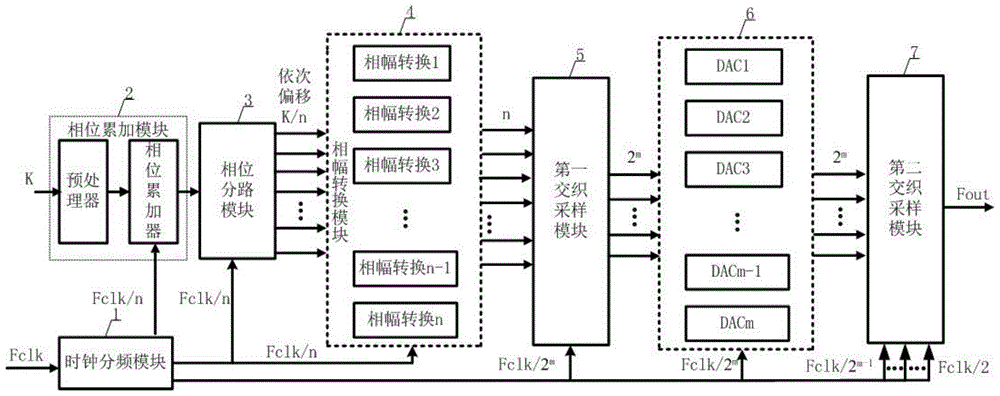
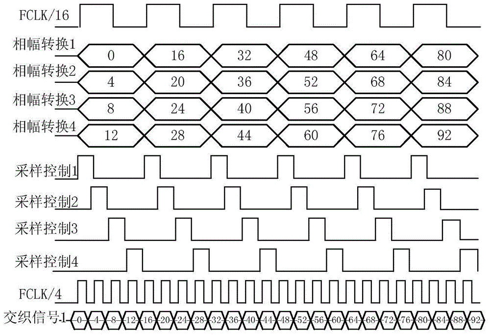
[0033] Such as Figure 2-5As shown, a preferred embodiment of a direct digital frequency synthesizer of the present invention, wherein n is 16, m is 2, and the clock frequency division module 1 divides the frequency of the system clock Fclk into 2 frequency division, 4 frequency division and 16 frequency division . The frequency division by 16 provides the working clock for the phase accumulation module 2, the phase division module 3 and the phase-amplitude conversion module 4, the frequency division by 4 provides the sampling clock for the first interleaving sampling module 5, and the frequency division by 2 provides sampling for the second interleaving sampling module 7 clock. The phase splitting module takes the accumulated phase based on one-sixteenth of the frequency control word K, and delays it by K / 16 in turn to obtain 16 groups of phase words, which are respectively entered into the phase-amplitude conversion module for conversion.

[0034] The data after the phase-...

Embodiment 2

[0038] Such as figure 2 As shown, a preferred embodiment of a direct digital frequency synthesizer of the present invention, wherein n is 24, m is 3, the frequency control word K enters the phase accumulation module 2 of the direct digital frequency synthesizer, and is preset by the phase accumulation module 2 The processor pre-processes, so that the phase can be divided into the expected 24 channels in the later phase division.

[0039] Such as figure 2 As shown, the clock frequency division module 1 divides the frequency of the system clock Fclk to obtain frequency division by 2, frequency division by 4, frequency division by 8 and frequency division by 24, respectively, and provide them to the following functional modules respectively. Frequency division by 2 and frequency division by 4 provides the sampling clock for the second interleaved sampling module 7, frequency division by 8 provides the sampling clock for the first interleaved sampling module 5, and frequency di...


PUM


Abstract

The invention relates to a direct digital frequency synthesizer capable of synthesizing a high-speed frequency. The direct digital frequency synthesizer comprises a phase accumulation module, a clock frequency division module, a phase shunting module, a phase-amplitude conversion module, a first interlaced sampling module, a digital-analogue conversion module and a second interlaced sampling module, wherein the clock frequency division module divides the frequency of a system clock and outputs the divided frequency; the phase accumulation module performs linear phase addition on a frequency control word under the control of a clock and outputs; the phase shunting module shunts a phase value into multiple paths of the phase values and outputs the phase values to the phase-amplitude conversion module; the phase-amplitude conversion module converts the multiple paths of the phase values into corresponding amplitude values; the first interlaced sampling module samples the amplitude values in an interlaced manner by regarding a frequency division clock as a sampling clock and outputs digital signals; the digital-analogue conversion module converts the digital signals into analogue signals; the second interlaced sampling module samples the analogue signals in the interlaced manner and outputs signals as same as the frequency of the system clock. The high-speed sampling frequency is obtained via a practical low-speed sampling clock, so that the direct digital frequency synthesizer improves the frequency of the output signals and reduces system power consumption.

Description

technical field [0001] The invention relates to the technical field of digital frequency synthesis, in particular to a direct digital frequency synthesizer capable of synthesizing high-speed frequencies. Background technique [0002] Digital frequency synthesis technology is a technology that synthesizes signals of various frequencies required by digital means, and finally converts them into analog signal output through a digital-to-analog converter. This technology has become one of the main technologies in today's frequency synthesis technology due to its unique characteristics: programmable, fast frequency hopping, high resolution, high frequency modulation accuracy, etc. It is widely used in mobile communications, military and commercial radar systems and other communication fields . [0003] With the development of the modern electronics industry and the reduction of semiconductor process size, the development trend of electronic chips is that the integration and speed...

Claims


Application Information

Patent Timeline
Patent Type & Authority Patents(China)
IPC IPC(8): H03L7/18H03L7/24
Inventor 万书芹张涛季惠才封晴于宗光
Owner 58TH RES INST OF CETC
Learn More