Optimized design method of airplane process equipment

A technology of process equipment and optimized design, applied in the direction of calculation, special data processing applications, instruments, etc., can solve the problems of inappropriate judgment of CNC machining surface and hole machining accuracy requirements, waste of processing costs, and difficult judgment, so as to reduce unnecessary The effects of testing work, shortening the processing cycle, and optimizing the frame design scheme

Inactive Publication Date: 2014-10-22
SHANGHAI SHANGFEI AIRCRAFT EQUIP MFG
View PDF1 Cites 5 Cited by
  • Summary
  • Abstract
  • Description
  • Claims
  • Application Information

AI Technical Summary

Problems solved by technology

[0002] In the traditional aircraft assembly process equipment, there are a large number of aircraft parts to be assembled, high positioning accuracy requirements for process equipment, strict coordination dimensions, and a large number of riveting work. Therefore, the size of the frame is often determined based on experience, resulting in The frame is bulky, bulky, excessive in strength, and poor in economy
[0003] At present, the basis for the manufacturing and inspection of process equipment parts is mostly drawings and three-dimensional digital models, especially for digital controls. When NC processing personnel compile NC machining programs based on drawings and digital models, it is not suitable to judge the machining accuracy of CNC machining profiles and holes. When it is required (especially for CNC parts with a large number of profiles and holes), if some parts need CNC finishing, and some parts are only used for CNC rough machining, it is judged by CNC processing technicians based on experience based on drawings. The surfaces and holes in the digital model are all finished by CNC, which not only prolongs the processing cycle, but also wastes a lot of unnecessary processing costs
At the same time, it is difficult for three-coordinate inspection personnel to judge the accuracy and requirements of the profiles and holes to be inspected. They often perform all or multiple inspections on uncertain profiles and holes, resulting in unnecessary inspection costs.

Method used


Image

  • Optimized design method of airplane process equipment
  • Optimized design method of airplane process equipment
  • Optimized design method of airplane process equipment

Examples


Embodiment Construction

[0026] The following are examples to introduce the above-mentioned optimization design methods respectively:

[0027] On the fuselage assembly frame of a certain model, the frame size is optimally designed, and the frame size is finally determined.

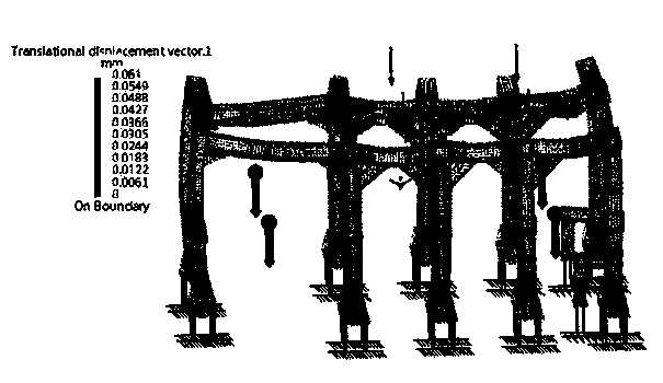
[0028] Figure 1 to Figure 5 It shows the strain diagram of the force analysis carried out by this optimal design method. The load of the jig is 8 tons, the safety factor is 4, and the maximum deformation allowed by the jig is δ (max) = 0.045 mm.

[0029] figure 1 It is the force analysis strain diagram of plan one (square steel pipe size is 250mm, thickness is 10mm, frame weight is 11757KG), the maximum deformation is 0.061mm, which does not meet the requirements.

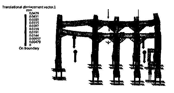
[0030] figure 2 It is the force analysis strain diagram of plan 2 (the size of the square steel pipe is 300mm, the thickness is 8mm, and the frame weight is 12083KG), and the maximum deformation is 0.049mm, which does not meet the requirements.
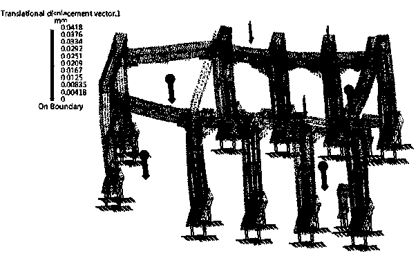
[0031] ...


PUM


Abstract

The invention discloses an optimized design method of airplane process equipment. Under the premise that fixture strength requirements are met, strain analysis is performed on a fixture of the process equipment, structural size is optimized, failing of a positioning function of the process equipment due to the fact that the fixture is insufficient in strength and wasting of a material due to the fact that the fixture is excessive in strength are avoided, weight after weight reducing is reduced by at least one tenth when compared with that of a conventional design method; in a three-dimensional math model, processing areas different in accuracy level are marked by colors, the math model together with a drawing is used during numerical-control processing and three-dimensional coordinate detection, processing accuracy requirements can be determined more visually, processing time can be reduced, and manufacturing and detection cost can be saved.

Description

technical field [0001] The invention relates to an optimal design method related to the design of aircraft technology equipment. Background technique [0002] In the traditional aircraft assembly process equipment, there are a large number of aircraft parts to be assembled, high positioning accuracy requirements for process equipment, strict coordination dimensions, and a large number of riveting work. Therefore, the size of the frame is often determined based on experience, resulting in The frame is bulky, bulky, excessive in strength, and poor in economy. [0003] At present, the basis for the manufacturing and inspection of process equipment parts is mostly drawings and three-dimensional digital models, especially for digital controls. When NC processing personnel compile NC machining programs based on drawings and digital models, it is not suitable to judge the machining accuracy of CNC machining profiles and holes. When it is required (especially for CNC parts with a ...

Claims


Application Information

Patent Timeline
Patent Type & Authority Applications(China)
IPC IPC(8): G06F17/50
Inventor 闫峰卜庆凤覃勇
Owner SHANGHAI SHANGFEI AIRCRAFT EQUIP MFG
Why Eureka
Try Eureka