
Jointing coal rock direct tensile test device and jointing coal rock direct tensile test method

A technology of tensile test and jointed coal rock, which is applied in the preparation of test samples and the use of stable tension/pressure to test the strength of materials, etc., can solve the problems of large deviation between test results and real values, and avoid bonding Difficult, avoid coal sample damage, avoid the effect of brittle coal cutting

Active Publication Date: 2014-10-22
平湖市精艺机械制造厂
View PDF9 Cites 4 Cited by
  • Summary
  • Abstract
  • Description
  • Claims
  • Application Information

AI Technical Summary

Problems solved by technology

[0004] An object of the present invention is to provide a kind of jointed coal rock direct tensile test device, this jointed coal rock direct tensile test device is used to solve in the coal rock tensile test, because stress concentration and eccentric tension cause test result to be different from For the larger problem of true value deviation, another object of the present invention is to provide the test method of this jointed coal rock direct tension test device

Method used


Image

  • Jointing coal rock direct tensile test device and jointing coal rock direct tensile test method
  • Jointing coal rock direct tensile test device and jointing coal rock direct tensile test method
  • Jointing coal rock direct tensile test device and jointing coal rock direct tensile test method

Examples


Embodiment Construction

[0031] The present invention will be further described below in conjunction with the accompanying drawings.

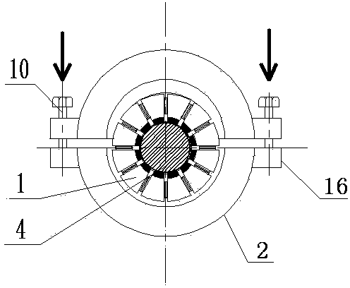
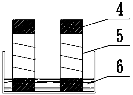
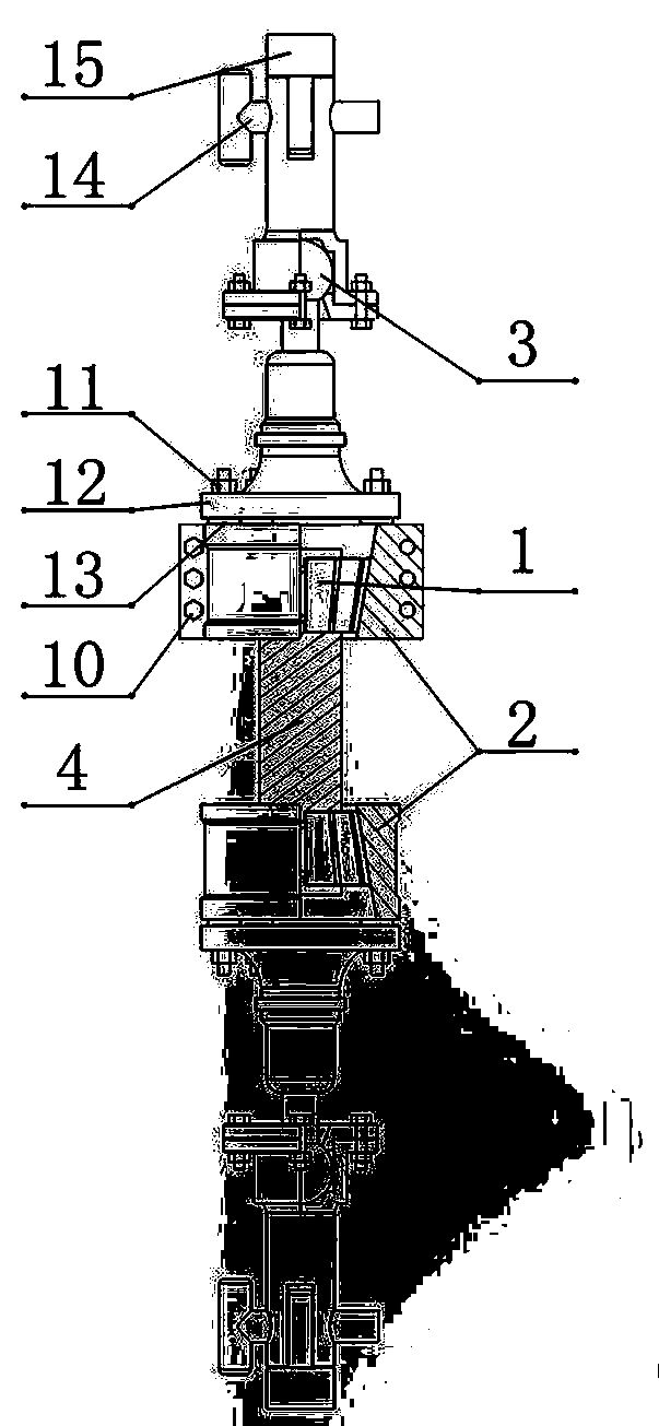
[0032] like figure 1 As shown in the figure, the jointed coal-rock direct tensile test device includes a taper sleeve of a card body, a spherical joint 3, and a tensile testing machine 15. The two ends of the coal sample 4 are respectively fastened by the taper sleeve of the card body, and each taper sleeve of the card body is connected. Corresponding ball joints 3 are connected to the tensile testing machine 15 . After the two ends of the coal sample 4 are respectively tightened by the taper sleeves of the card body, they are connected to the tensile testing machine 15 through the ball joint 3, and the tensile testing machine 15 conducts the tensile test on the coal sample 4. 1. Set it on the end of coal sample 4, and then install the cone sleeve 2. The outer surface of the card body 7 is completely fit with the inner wall of the cone sleeve 2. When stretching, the p...


PUM

PropertyMeasurementUnit
Thicknessaaaaaaaaaa
Compressive strengthaaaaaaaaaa

Abstract

The invention relates to a jointing coal rock direct tensile test device and a jointing coal rock direct tensile test method. The jointing coal rock direct tensile test device comprises clamping body taper sleeves, a spherical joint and a tensile testing machine, wherein both ends of a coal sample are respectively tightly sleeved by the clamping body taper sleeves, each clamping body taper sleeve is connected with the corresponding spherical joint, and the spherical joint is connected with the tensile testing machine; each clamping body taper sleeve is formed by sleeving a taper sleeve out of an annular wedge-shaped sleeve, and the annular wedge-shaped sleeve comprises twelve clamping bodies, spring joints and rubber gaskets; the adjacent clamping bodies are sequentially connected end to end through the spring joints to form the annular wedge-shaped sleeve, the outer surfaces of the clamping bodies are in arc shapes, the longitudinal sections of the clamping bodies are in trapezoidal shapes, and the inner surfaces of the clamping bodies are provided with the rubber gaskets; one ends of the spring joints are provided with connecting plates, and the other ends of the spring joints are provided with connecting columns; the top ends of the connecting columns are provided with axial center grooves, and two side walls of the center grooves are provided with pin holes; the spring joints are fixedly connected with the tensile testing machine through the center grooves. The jointing coal rock direct tensile test device disclosed by the invention can effectively prevent the coal sample from being damaged due to excessive pressure of a clamp on the coal sample and reduces the influence of stress concentration on a test result.

Description

technical field [0001] The invention relates to rock tensile test technology in the fields of rock mechanics engineering, petroleum engineering, mining engineering and the like, in particular to a jointed coal rock direct tensile test device and a test method. Background technique [0002] The tensile strength of rock is an important mechanical index. In the past, when studying the tensile properties of rocks and determining the tensile strength, the test methods usually used can be divided into two categories: one is the direct measurement method, that is, the uniaxial tensile test. ; Another type of method is the indirect measurement method, including the Brazilian splitting method, the bending test method and the indentation test method. The most commonly used indirect measurement method is the Brazilian splitting test. However, due to the development of coal bedding and the cutting of joints and fissures, when the Brazilian splitting method is used for the test, the coal...

Claims


Application Information

Patent Timeline
IPC IPC(8): G01N3/08G01N1/28
Inventor 李玉伟艾池张军史晓东李银朋陶飞宇
Owner 平湖市精艺机械制造厂
Learn More