
Turbocharger

A turbocharger, turbine technology, applied in machine/engine, engine components, internal combustion piston engine, etc., can solve problems such as not clarifying the best effect, achieve smooth flow, reduce entropy increase, and weaken turbulent flow.

Active Publication Date: 2017-05-10
WUXI CUMMINS TURBO TECH
View PDF7 Cites 0 Cited by
  • Summary
  • Abstract
  • Description
  • Claims
  • Application Information

AI Technical Summary

Problems solved by technology

[0010] Although the patent CN201310700713.4 proposes a transition joint design that can improve turbine efficiency, it does not clarify which structure can achieve the best effect

Method used


Image

  • Turbocharger
  • Turbocharger
  • Turbocharger

Examples


Embodiment Construction

[0026] The present invention will be further described below in conjunction with specific drawings and embodiments.

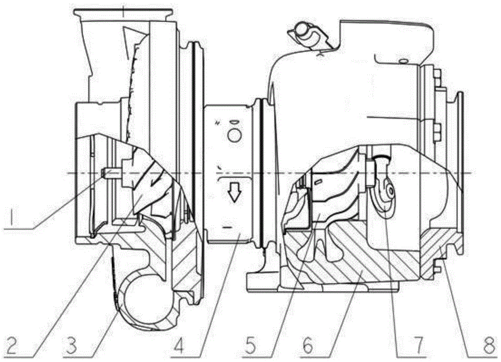
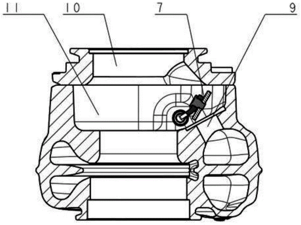
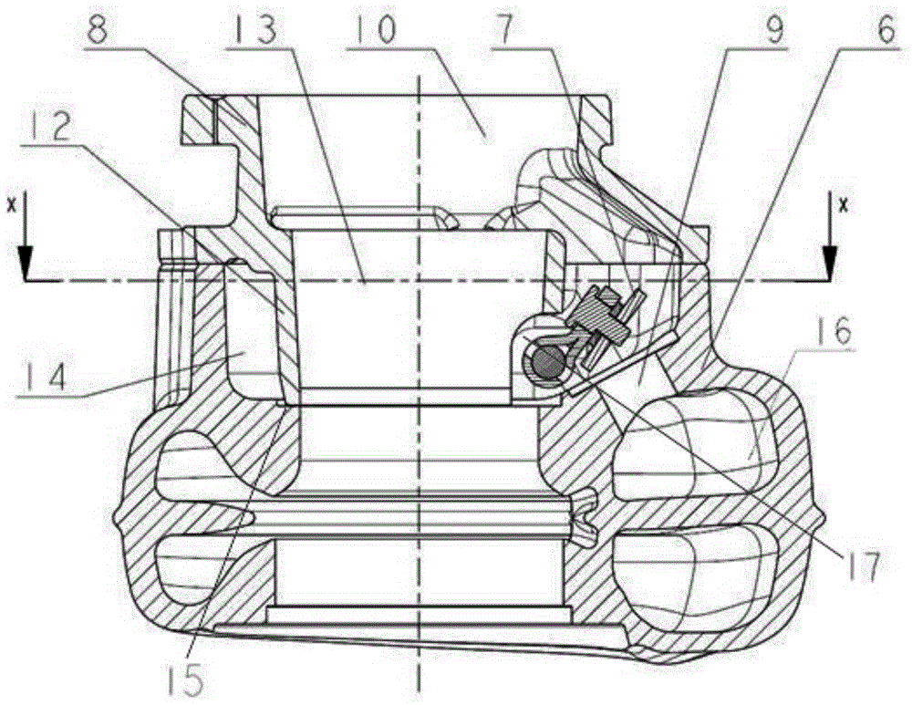
[0027] Such as image 3 , 4 As shown, a turbocharger of the present invention includes a turbine casing 6 with a flow passage 16, a bypass passage 9 communicating with the flow passage 16 is provided on the turbine casing 6, and the bypass passage 9 A bypass valve 7 is provided on the top, and a transition joint 8 is fixedly connected to the installation surface of the turbine casing 6. A partition wall 12 is provided on the side where the transition joint 8 is connected to the turbine casing 6, and the partition wall 12 extends into the turbine casing. In some special cases, due to space constraints, the positions of the partition wall 12 and the bypass valve 7 will partially overlap , at this time, an installation groove 17 can be provided on the partition wall 12 corresponding to the bypass valve 7; in other cases, there is no installation groove 17 here, ...


PUM


Abstract

The invention relates to a turbocharger, in particular to a turbocharger with a dividing wall on the transition joint, which has the functions of flow splitting and guiding, including a turbine casing with a flow channel, and the turbine The housing is provided with a bypass channel connecting the flow channel, and a bypass valve is provided on the bypass channel, and a transition joint is fixedly connected to the installation surface of the turbine housing, and the feature is that the transition joint is connected with the turbine housing A partition wall is provided on one side, and the partition wall extends into the inner cavity of the turbine casing and divides the turbine casing into a central area and a peripheral area; an installation slot is opened on the partition wall corresponding to the bypass valve. The supercharger can significantly increase the bypass volume, and at the same time ensure that the efficiency of the turbine is basically unchanged or even slightly improved, so as to meet the performance requirements of the engine.

Description

technical field [0001] The invention relates to a turbocharger, in particular to a turbocharger with a dividing wall added to a transition joint, which has the functions of flow diversion and guiding. Background technique [0002] A turbocharger is a device that delivers air to the intake manifold of an internal combustion engine at a pressure higher than atmospheric pressure. A common turbocharger mainly includes a turbine wheel driven by exhaust gas, which is installed on the center of rotation of the turbine casing, and the turbine casing is connected to the outlet of the exhaust pipe of the engine. Exhaust gases from the exhaust pipe of the engine rotate the turbine wheel, and the rotation of the latter turbine wheel rotates the compressor wheel located in the compressor housing and mounted on the other end of the turbine shaft. The compressor compresses and sends air to the intake manifold of the engine. The turbine shaft is generally supported by floating and thrust ...

Claims


Application Information

Patent Timeline
Patent Type & Authority Patents(China)
IPC IPC(8): F02B37/18F01D25/24
CPCY02T10/12
Inventor 巩景林金建交
Owner WUXI CUMMINS TURBO TECH
Learn More