
Sawing spray valve block

A spray valve and sawing technology, applied in metal sawing equipment, attachments of sawing machines, metal processing equipment, etc., can solve the problems of saw blade heating, affecting the practical life of saw blade, and inability to directly cool saw blade, etc. The effect of the work environment

Active Publication Date: 2014-10-22
佛山市南海万格士机械设备有限公司
View PDF6 Cites 0 Cited by
  • Summary
  • Abstract
  • Description
  • Claims
  • Application Information

AI Technical Summary

Problems solved by technology

However, during the cutting process, due to the high-speed rotation of the saw blade, an air curtain will be formed around the saw blade, so that the coolant cannot directly cool the saw blade, so that the heat generation problem of the saw blade is still relatively serious, which affects the practical life of the saw blade

Method used


Image

  • Sawing spray valve block
  • Sawing spray valve block

Examples


Embodiment Construction

[0013] The idea, specific structure and technical effects of the present invention will be clearly and completely described below in conjunction with the embodiments and accompanying drawings, so as to fully understand the purpose, features and effects of the present invention. Apparently, the described embodiments are only some of the embodiments of the present invention, rather than all of them. Based on the embodiments of the present invention, other embodiments obtained by those skilled in the art without creative efforts belong to The protection scope of the present invention. In addition, all the connection / connection relationships mentioned in this article do not refer to the direct connection of components, but mean that a better connection structure can be formed by adding or reducing connection accessories according to specific implementation conditions. The various technical features in the invention can be combined interactively on the premise of not conflicting wi...


PUM


Abstract

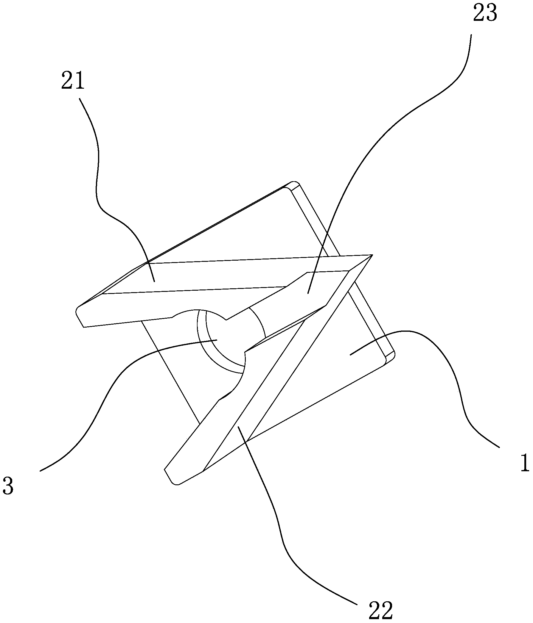
The invention discloses a sawing spray valve block. The sawing spray valve block comprises a plate-shaped base, two stop blocks and an injection port, the stop blocks include a left stop block and a right stop block, lower end faces of the stop blocks are fixed on the same plane of the base, the left stop block and the right stop block are intersected by an acute angle, the injection port runs through the base and intersects with the left stop block and the right stop block, and a cutter groove is formed downwards from the upper end of the intersection of the left stop block and the right stop block. The sawing spray valve block is mounted on the upper portion of a saw blade which is positioned in the cutter groove between the stop blocks, when the saw blade works, air curtains generated by the saw blade is crushed by the stop blocks when passing through the stop blocks, and cooling liquid sprayed from the injection port is enabled to be sprayed on blades directly and is driven to be recycled along the blades by high-speed recycling of the blades, so that the cooling liquid is brought from the upper portion of the saw blade to the lower portion of a sawing work portion to cool the saw blade.

Description

technical field [0001] The invention relates to a saw blade cooling device for cooling the saw blade in a cutting machine. Background technique [0002] In the aluminum profile production equipment, the extruded aluminum rods need to be cut and packaged with a cutting machine. In the prior art, saw blades are usually used for cutting. Since the aluminum rods just out of the oven are relatively thick, cutting time A lot of heat will be generated. In order to protect the saw blade from being damaged, coolant will be sprayed at the cutting position to reduce the temperature of the saw blade and ensure smooth cutting operations. However, during the cutting process, due to the high-speed rotation of the saw blade, an air curtain will be formed around the saw blade, so that the coolant cannot directly cool the saw blade, so that the heat generation problem of the saw blade is still relatively serious, which affects the practical life of the saw blade . Contents of the invention...

Claims


Application Information

Patent Timeline
Patent Type & Authority Applications(China)
IPC IPC(8): B23D59/02
Inventor 林开超
Owner 佛山市南海万格士机械设备有限公司
Learn More