WRGB (white, red, green and blue) color saturation enhancing method

A saturation and color technology, applied in the field of improving WRGB color saturation, can solve problems such as watermarks and uneven grayscale transitions

Active Publication Date: 2014-10-15
TCL CHINA STAR OPTOELECTRONICS TECH CO LTD
View PDF8 Cites 13 Cited by
  • Summary
  • Abstract
  • Description
  • Claims
  • Application Information

AI Technical Summary

Problems solved by technology

[0007] The purpose of the present invention is to provide a method for improving the color saturation of WRGB, so that the color saturation of the liquid crystal display panel is improved, the display effect is more vivid, the picture quality is better, and the gray scale transition problem existing in the existing WRGB technology is solved. Smoothness, watermark phenomenon in some grayscales, etc.

Method used


Image

  • WRGB (white, red, green and blue) color saturation enhancing method
  • WRGB (white, red, green and blue) color saturation enhancing method
  • WRGB (white, red, green and blue) color saturation enhancing method

Examples


Embodiment Construction

[0071] In order to further illustrate the technical means adopted by the present invention and its effects, the following describes in detail in conjunction with preferred embodiments of the present invention and accompanying drawings.

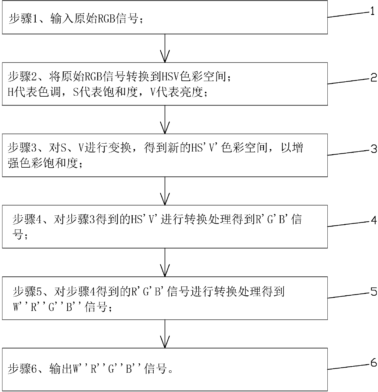
[0072] see figure 1 , is a flowchart of an embodiment of a method for improving WRGB color saturation in the present invention, including the following steps:

[0073] Step 1. Input the original RGB signal.

[0074] Step 2. Convert the original RGB signal to HSV color space.

[0075] H stands for Hue, S for Saturation, and V for Brightness.

[0076] The conversion formula used in step 2 is:

[0077]

[0078] s = 0 , if max = 0 max - ...


PUM


Abstract

The invention provides a WRGB color saturation enhancing method. The method comprises the following steps of, firstly, inputting original RGB (red, green and blue) signals; secondly, converting the original RGB signals into an HSV (hue, saturation and value) color space; thirdly, transforming S and V to obtain a new HS'V' color space and to enhance the color saturation; fourthly, converting the HS'V' color space obtained in the third step to obtain R'G'B' signals; fifthly, converting the R'G'B' signals obtained in the fourth step to obtain W'R'G'B' signals; sixthly, outputting the W'R'G'B' signals. The WRGB color saturation enhancing method can enhance the color saturation of a liquid crystal display panel, achieve brighter display effects and higher picture quality and solve the problems of gray scale transition unsmoothness, watermarks in certain gray scales and the like in existing WRGB technologies.

Description

technical field [0001] The invention relates to the field of display technology, in particular to a method for improving WRGB color saturation. Background technique [0002] Flat panel display devices such as Liquid Crystal Display (LCD) and Organic Light Emitting Diode (OLED) have gradually replaced CRT displays and become mainstream products in today's market. The display panel is an important part of flat panel display devices such as LCD and OLED. For LCD, the structure of its liquid crystal display panel is generally composed of a color filter substrate (Color Filter, CF), a thin film transistor array substrate (Thin Film Transistor Array Substrate, TFT Array Substrate), and a configuration on the two substrates Its working principle is to control the rotation of the liquid crystal molecules in the liquid crystal layer by applying a driving voltage on the two glass substrates, and refract the light provided by the backlight module to generate images. [0003] A conven...

Claims


Application Information

Patent Timeline
Patent Type & Authority Applications(China)
IPC IPC(8): G09G3/36
CPCH04N9/64G09G3/3607G09G2360/16G09G3/2003G09G3/2074G09G2340/06G09G3/36G09G5/02G09G3/2011G09G2300/0452G09G2320/0666
Inventor 樊勇
Owner TCL CHINA STAR OPTOELECTRONICS TECH CO LTD
Why Eureka
Try Eureka