
Relay protection fiber channel intelligent monitoring system

An optical fiber channel and intelligent monitoring technology, applied in transmission monitoring/testing/fault measurement systems, optical fiber transmission, transmission systems, etc., can solve problems such as cumbersome message information, inability to quickly locate faulty optical fibers, and numerous equipment in substations. achieve high reliability

Inactive Publication Date: 2014-10-08
STATE GRID CORP OF CHINA +1
View PDF1 Cites 3 Cited by
  • Summary
  • Abstract
  • Description
  • Claims
  • Application Information

AI Technical Summary

Problems solved by technology

[0003] The traditional fiber channel monitoring method generally adopts the method of uploading messages, but there are many devices in the substation and the message information is cumbersome, so it cannot quickly locate the faulty fiber

Method used


Image

  • Relay protection fiber channel intelligent monitoring system
  • Relay protection fiber channel intelligent monitoring system

Examples


Embodiment Construction

[0019] In order to clearly illustrate the technical features of this solution, the present invention will be described in detail below through specific implementation modes and in conjunction with the accompanying drawings. The following disclosure provides many different embodiments or examples for implementing different structures of the present invention. To simplify the disclosure of the present invention, components and arrangements of specific examples are described below. Furthermore, the present invention may repeat reference numerals and / or letters in different instances. This repetition is for the purpose of simplicity and clarity and does not in itself indicate a relationship between the various embodiments and / or arrangements discussed. It should be noted that components illustrated in the figures are not necessarily drawn to scale. Descriptions of well-known components and processing techniques and processes are omitted herein to avoid unnecessarily limiting the...


PUM


Abstract

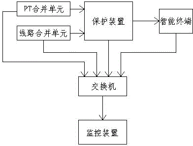
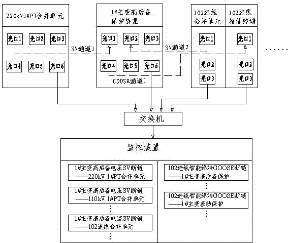
A relay protection fiber channel intelligent monitoring system comprises a merging unit, a protection device, an intelligent terminal, a switch and a monitoring device, wherein the protection device is connected with the merging unit through an optical fiber, and the intelligent terminal is connected with the protection device through an optical fiber. The switch is an optical fiber switch and is respectively connected with the merging unit, the protection device, the intelligent terminal and the monitoring device so as to monitor optical fiber channels among the merging unit, the protection device and the intelligent terminal and send optical fiber channel monitoring information to the monitoring device to be displayed. A local monitoring device of an intelligent substation is provided with optical fiber chain scission photon boards, corresponding optical fiber chain scission photon boards flicker once optical fiber chain scission faults occur, and operation and maintenance workers can perform quick positioning on faulted optical fibers.

Description

technical field [0001] The invention relates to a monitoring device for an optical fiber channel in an intelligent substation, in particular to an intelligent monitoring system for a relay protection optical fiber channel. Background technique [0002] With the development of power systems, smart substations are increasing. Different from conventional substations, optical fibers are used in smart substations instead of traditional secondary cables. The introduction of optical fibers greatly reduces traditional secondary wiring. According to human observation, once the fiber channel breaks down, it will affect the data sampling and output of the protection device, causing the protection to malfunction or refuse to operate. The traditional fiber channel monitoring method generally adopts the method of uploading messages, but there are many devices in the substation, and the fiber channel monitoring information is easily submerged in the cumbersome message information, and it i...

Claims


Application Information

Patent Timeline
Patent Type & Authority Applications(China)
IPC IPC(8): H04B10/07H04B10/25H04L12/24
Inventor 高兆丽彭克沈通王学亮
Owner STATE GRID CORP OF CHINA
Learn More