Hydraulic control unscrewed one-way valve
A one-way valve and hydraulic control technology, which is applied in the direction of fluid pressure actuators, servo motor components, mechanical equipment, etc., can solve the problem of one-way valves with few spools
Active Publication Date: 2014-10-08
ZHEJIANG UNIV +1
View PDF6 Cites 4 Cited by
- Summary
- Abstract
- Description
- Claims
- Application Information
AI Technical Summary
Problems solved by technology
Now the common one-way valve spools are all sliding, and there are few check valves with spool rotation.
Method used
View moreImage
Smart ImageViewing Examples
Examples
Embodiment Construction
Login to View More PUM
 Abstract
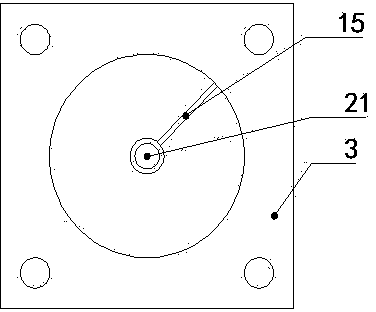
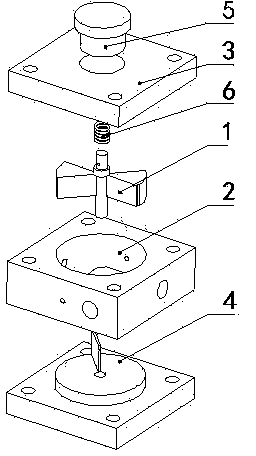
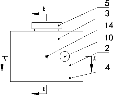
The invention discloses a hydraulic control unscrewed one-way valve which comprises a valve core, a valve body, a first end cover, a second end cover, a torsion spring and an adjusting nut, wherein a first check block and a second check block are arranged on the outer wall of the valve core at intervals along the circumferential direction; a third check block is arranged on the valve body; a fourth check block is arranged on the second end cover or the inner wall of the valve body; an oil opening P1, an oil opening P2, an oil opening K, an oil opening T1 and an oil opening T2 are formed in the valve body; the adjusting nut is connected with the valve core through the torsion spring; the valve core can be pushed by oil from the oil opening P1 to rotate, so that the oil opening P1 is communicated with the oil opening P2; the valve core cannot rotate through the pushing of oil from the oil opening P2 to rotate. The hydraulic control unscrewed one-way valve disclosed by the invention has the benefits that under the condition that the oil is not controlled, the oil entering the oil opening P1 can flow to the oil opening P2 and the oil entering the oil opening P2 cannot flow to the oil opening P1; under the condition that the oil is controlled, the oil can flow in two ways, so that one-way flowing or two-way flowing of the oil can be controlled.
Description
technical field The invention relates to a hydraulically controlled unscrewable one-way valve. Background technique The hydraulic check valve is a common component in the hydraulic system. The ordinary check valve controls the forward conduction of the oil circuit and the reverse cutoff. On the basis of the ordinary check valve, the hydraulic control check valve adds a control oil port. Under the action of the control oil, the one-way valve can be bidirectionally conducted. And now common one-way valve spools all slide, and there are few check valves with spool rotation. Contents of the invention The object of the present invention is to provide a hydraulically controlled unscrewable check valve, which can control the one-way conduction or two-way conduction of the hydraulic system by controlling the rotational movement of the valve core. In order to achieve the above object, the technical solution adopted by the present invention is: the hydraulically controlled unsc...
Claims
Login to View More Application Information
Patent Timeline
 Patent Type & Authority Applications(China)
IPC IPC(8): F15B13/02
Inventor 龚国芳周鸿彬韩冬王鹤刘毅刑星
Owner ZHEJIANG UNIV
Features
- R&D
- Intellectual Property
- Life Sciences
- Materials
- Tech Scout
- Unparalleled Data Quality
- Higher Quality Content
- 60% Fewer Hallucinations
Learn More Browse by: Latest US Patents, China's latest patents, Technical Efficacy Thesaurus, Application Domain, Technology Topic, Popular Technical Reports.
© 2025 PatSnap. All rights reserved.Legal|Privacy policy|Modern Slavery Act Transparency Statement|Sitemap|About US| Contact US: help@patsnap.com


