
Automatic parking system

An automatic parking and parking technology, which is applied in the field of automobile control devices, can solve the problems of high cost, high price, unfavorable popularization, etc., and achieve the effect of simple structure and low cost

Inactive Publication Date: 2014-10-08
蒋国祥
View PDF6 Cites 2 Cited by
  • Summary
  • Abstract
  • Description
  • Claims
  • Application Information

AI Technical Summary

Problems solved by technology

When it is necessary to release the stationary state, the brake can be released by simply tapping the accelerator, which brings great convenience to the driver; but at present, this automatic parking system is controlled by a computer and needs to be equipped with various sensors. The price is high, and only high-end vehicles are equipped with this system; for low-end vehicles, the cost is too high, which is not conducive to popularization

Method used


Image

  • Automatic parking system
  • Automatic parking system
  • Automatic parking system

Examples


Embodiment 1

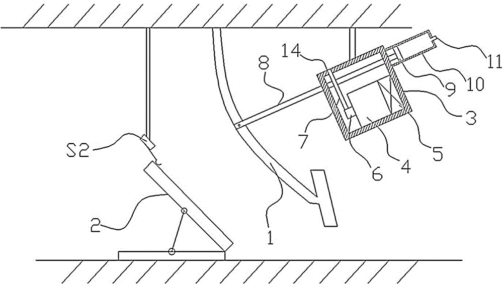
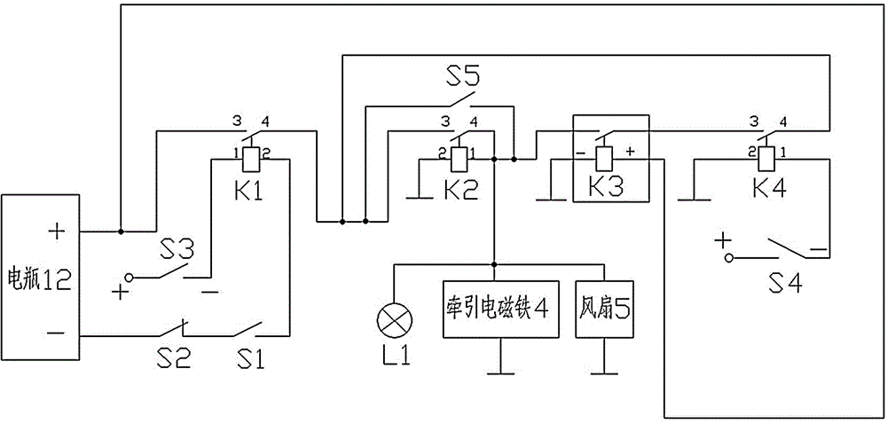
[0015] Such as figure 1 As shown, an automatic parking system provided by an embodiment of the present invention, for an automatic transmission car, includes a brake lever 8 and a housing 3 arranged above the brake pedal 1. The housing 3 is provided with a traction electromagnet 4, and the housing The top of the body 3 is provided with a card slot 14, and a card 7 is provided in the card slot 14. One end of the card 7 is fixedly connected with the armature 6 in the traction electromagnet 4; the brake lever 8 penetrates the housing 3 and the card 7, and They are slidingly fitted with the housing 3 and the card 7, and one end of the brake rod 8 is fixedly connected with the brake pedal 1; the outer side of the housing 3 is provided with a piston cylinder 10, the piston cylinder 10 is provided with a damping piston 9 and a brake rod 8 The other end is connected with the damping piston 9, the outer end of the piston cylinder 10 is provided with a vent 11; the casing 3 is also provi...

Embodiment 2

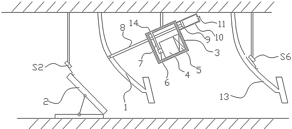
[0019] Such as image 3 As shown, an automatic parking system provided by an embodiment of the present invention, for a manual transmission car, on the basis of the structure of the first embodiment, the device further includes a clutch switch S6 linked with the clutch pedal 13, and when the clutch pedal 13 is depressed When the clutch switch S6 is closed, when the clutch pedal 13 is released, the clutch switch S6 is opened; Figure 4 As shown, on the basis of the electrical control device of the first embodiment, the clutch switch S6 is connected in parallel with both ends of the throttle switch S2. When the car is parked at a red light, uphill or downhill, the braking process is the same as in the first embodiment. When the brake needs to be unlocked, step on the clutch pedal 13, and then step on the accelerator pedal 2 in gear, and the accelerator switch S2 is turned off. On, the clutch switch S6 is closed, the circuit is still connected, and the brake is not released. At th...


PUM


Abstract

The invention discloses an automatic parking system comprising a brake rod and a shell arranged above a brake pedal, the shell is internally provided with a traction electromagnet, a clamping groove is formed in the top of the shell and is internally provided with a clamping piece, one end of the clamping piece is fixedly connected with an armature in the traction electromagnet, the brake rod penetrates through the shell and the clamping piece and is in sliding fit with the shell and the clamping piece, and one end of the brake rod is fixedly connected with the brake pedal. The automatic parking system further comprises a brake switch controlling the traction electromagnet to be powered on and an accelerator switch which is linked with an accelerator pedal and controls the traction electromagnet to be powered off. The brake switch controls the traction electromagnet to be powered on, so that the clamping piece moves to clamp the brake rod connected with the brake pedal, and the position of the brake pedal is kept; the accelerator switch controls the traction electromagnet to be powered off, so that the clamping piece resets to release the brake rod, the brake state is released, computer control is not needed, the structure is simple, the cost is low, and the automatic parking system is applicable to wide use and popularization.

Description

Technical field [0001] The invention relates to the field of automobile control devices, in particular to an automatic parking system. Background technique [0002] It is well known that all cars are equipped with a parking brake lever, commonly known as a handbrake, which is used to stabilize the vehicle after the vehicle is stopped, to avoid accidents caused by the vehicle slipping on a slope or waiting for a red light to stop, and operate according to regulations Handbrake requires the driver to have skilled driving skills. For car owners who often walk and stop in the city, they often cause unnecessary accidents due to paralysis. Therefore, the automatic parking system came into being. The automatic parking system is a A function that automatically pulls the handbrake for you. After starting this function, for example, when you stop and wait for a traffic light, it is equivalent to not having to pull the handbrake. This function is especially suitable for going up and down sl...

Claims


Application Information

Patent Timeline
Patent Type & Authority Applications(China)
IPC IPC(8): B60T7/12
Inventor 蒋国祥
Owner 蒋国祥
Learn More