
Method and arrangement for RRC switching

A technology of state switching and user equipment, applied in advanced technology, electrical components, power management, etc., can solve problems such as slowness and less than optimal performance, and achieve the effect of minimizing power consumption

Inactive Publication Date: 2014-10-01
TELEFON AB LM ERICSSON (PUBL)
View PDF2 Cites 10 Cited by
  • Summary
  • Abstract
  • Description
  • Claims
  • Application Information

AI Technical Summary

Problems solved by technology

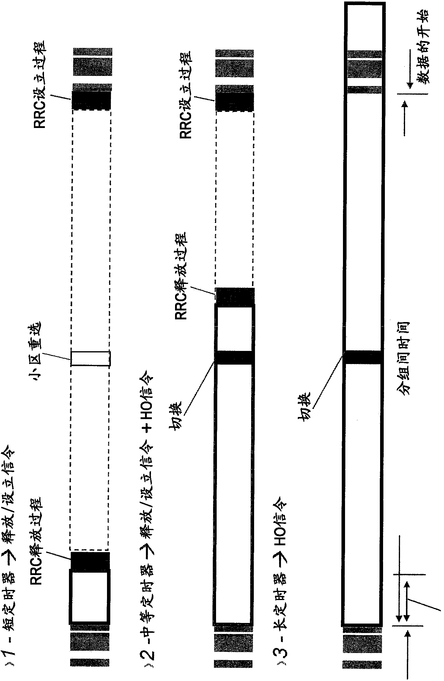
[0018] One problem with the prior art handover method described above is that it is a very sluggish approach which will result in less than optimal performance at high mobility levels

Method used


Image

  • Method and arrangement for RRC switching
  • Method and arrangement for RRC switching
  • Method and arrangement for RRC switching

Examples


Embodiment Construction

[0038] Throughout the drawings, the same reference numerals are used for similar or corresponding elements. Although primarily described in the context of an LTE system, the present disclosure is equally applicable to similar systems, such as WCDMA (Wideband Code Division Multiple Access) systems.

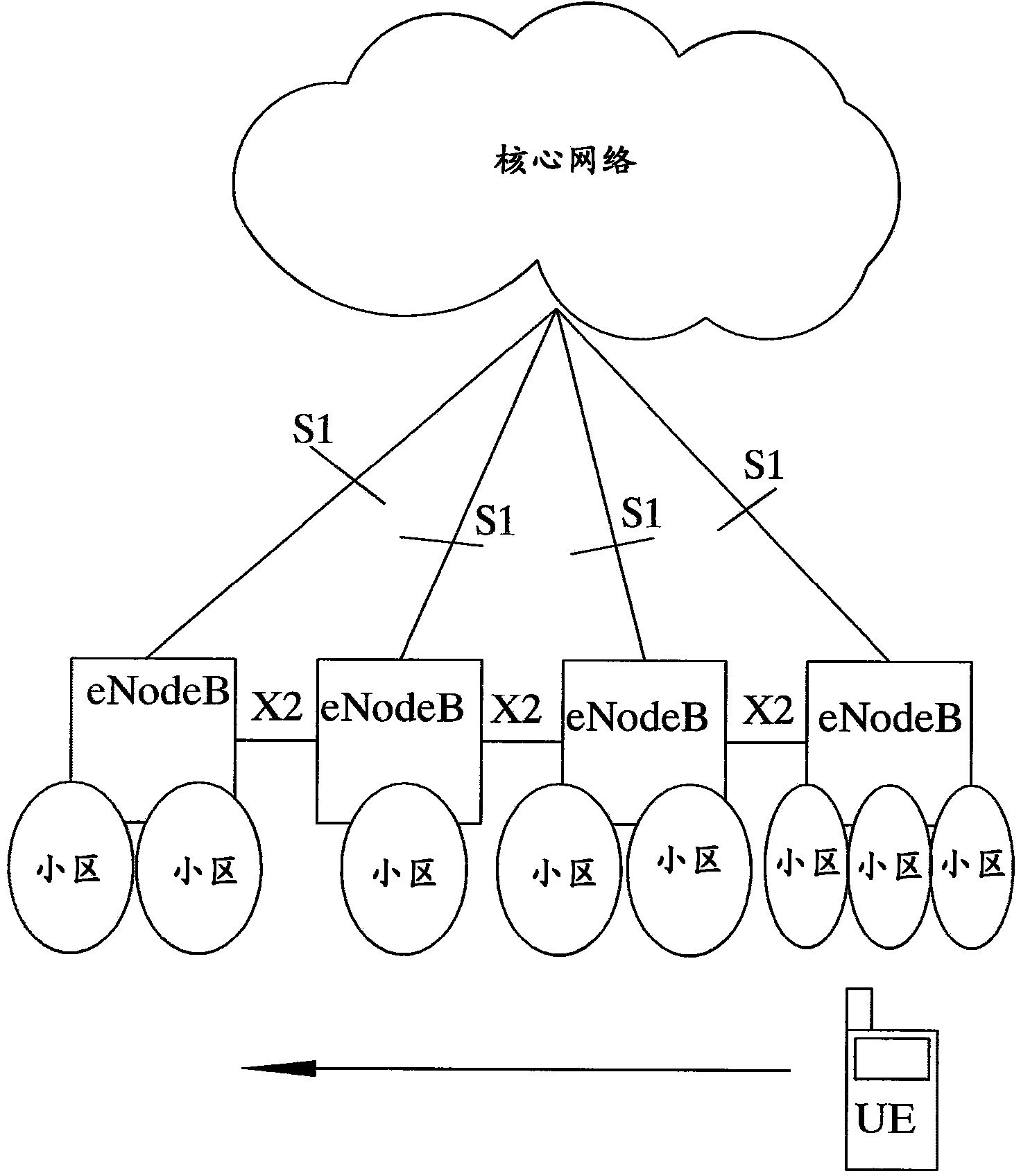
[0039] figure 2 The simplified radio communication network illustrated in , comprises a plurality of radio base stations (eNodeBs), each of which has the possibility to manage one or more radio cells (called cells for simplicity). For example, a radio base station manages one or more cells, such as a particular cell currently serving user equipments (UEs). This cell is called a source cell or serving cell for this particular user equipment. Another radio base station manages one or more cells, and yet another radio base station manages one or more cells. The cells managed by the radio base stations are called handover candidate cells for the UE, and the UE may handover to any o...


PUM


Abstract

In a method of controlling RRC (Radio Resource Control) state switching in a wireless communication system, adaptively controlling (S40) RRC state switching between an idle state and a connected state for a user equipment based on at least a detected mobility measure for said user equipment.

Description

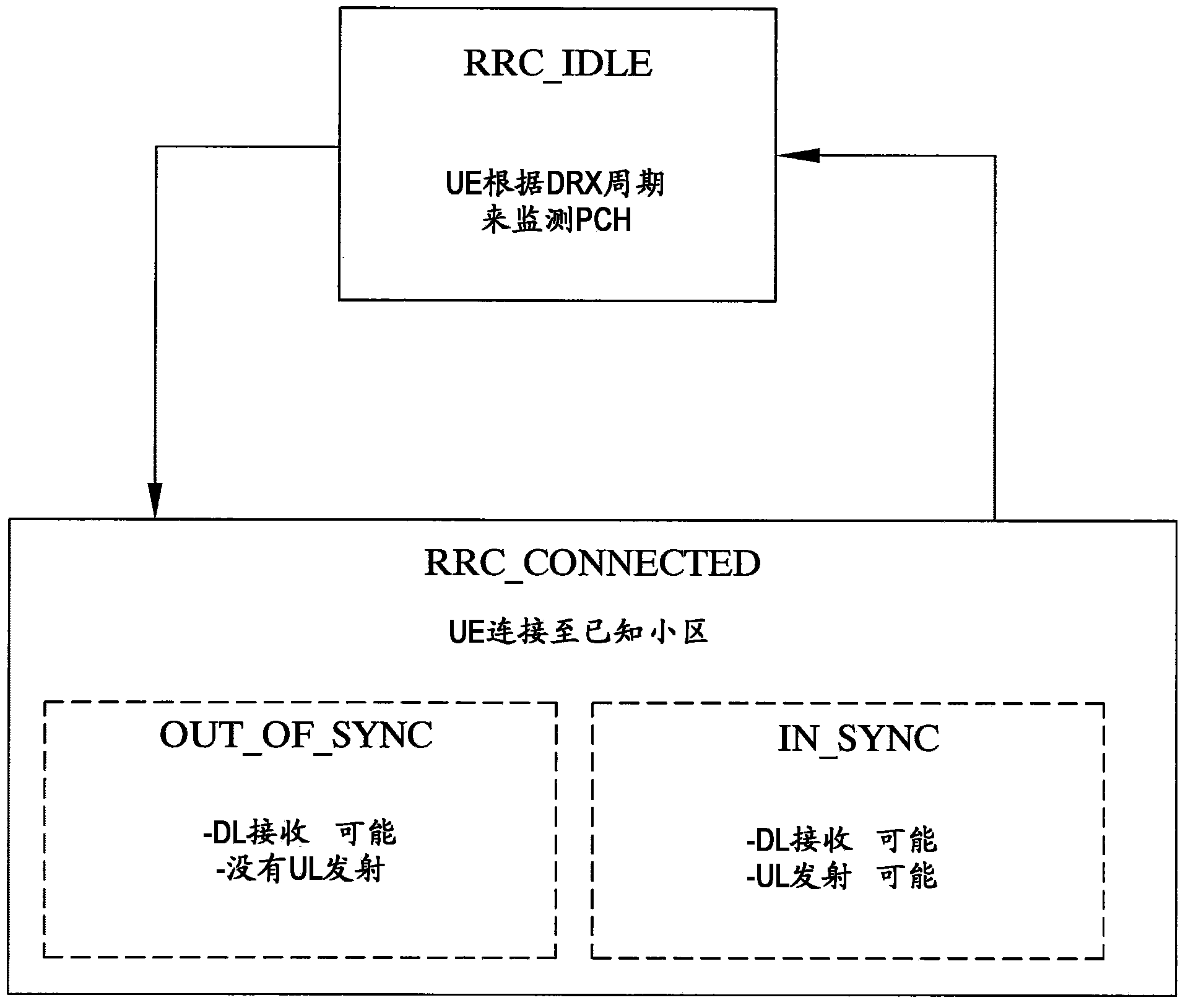
technical field [0001] The present disclosure relates generally to wireless communication systems, and in particular to the management of RRC (Radio Resource Control) state switching in such systems. Background technique [0002] An essential feature in cellular radio communication systems is handover (HO). Handover is the main function used to support mobility in the network. When a mobile terminal or user equipment (UE) moves in a cellular network, when the signal from the current cell is too weak to support the current radio link and / or when it is decided that another cell has a better possibility to support the When the radio communication of the user terminal, it must change the serving cell. [0003] LTE (Long Term Evolution) is a radio access technology standardized by 3GPP (3rd Generation Partnership Project). The LTE system uses Orthogonal Frequency Division Multiplexing (OFDM) as a multiple access technique (referred to as OFDMA) in downlink from system nodes to...

Claims


Application Information

Patent Timeline
Patent Type & Authority Applications(China)
IPC IPC(8): H04W76/04
CPCH04W52/0254H04W76/27Y02D30/70
Inventor 卢前溪范锐
Owner TELEFON AB LM ERICSSON (PUBL)
Learn More