
Composite buffer area image display method and device

An image display device and image display technology are applied in the directions of image data processing, image data processing, digital output to display equipment, etc., which can solve the problems of large CPU resources, low efficiency and cost of composite buffer image display, and achieve reduction Occupation of CPU resources, avoiding the calculation of overlapping areas, and improving efficiency

Inactive Publication Date: 2014-10-01
GUANGDONG VTRON TECH CO LTD
View PDF2 Cites 13 Cited by
  • Summary
  • Abstract
  • Description
  • Claims
  • Application Information

AI Technical Summary

Problems solved by technology

However, using this method usually consumes a lot of CPU resources, resulting in low efficiency of composite buffer image display

Method used


Image

  • Composite buffer area image display method and device
  • Composite buffer area image display method and device

Examples


Embodiment Construction

[0020] In order to make the object, technical solution and advantages of the present invention more clear, the present invention will be further described in detail below in conjunction with the accompanying drawings and embodiments. It should be understood that the specific embodiments described here are only used to explain the present invention, not to limit the present invention.

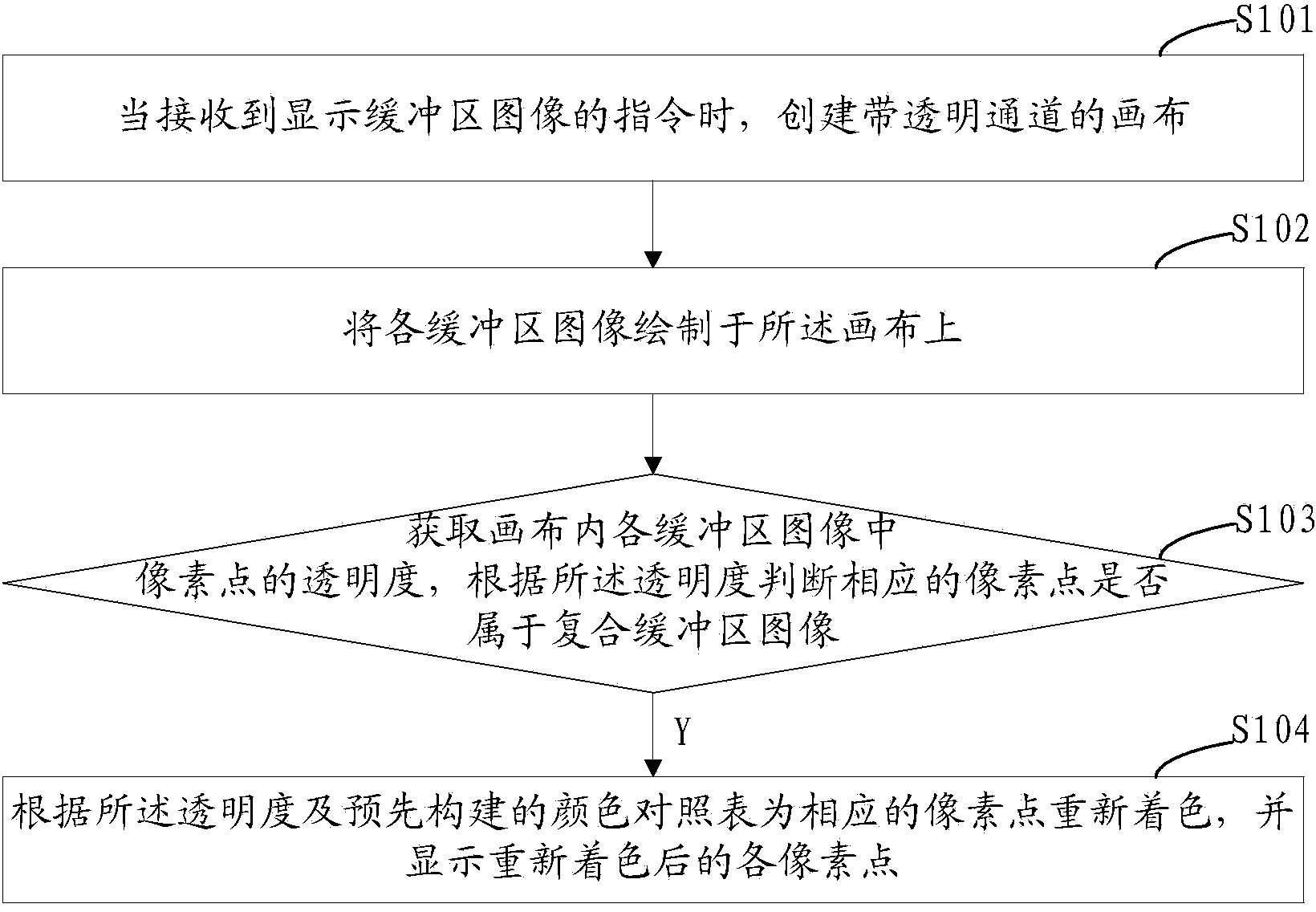
[0021] see figure 1 Shown, a composite buffer image display method, comprising the following steps:

[0022] Step S101, when receiving an instruction to display a buffer image, create a canvas with a transparent channel; then go to step S102. It should be noted that the canvas has a transparent channel, so the transparency of each pixel in the canvas can be set as required. For example, in one embodiment, the transparency of each pixel in the canvas is zero. Usually, before the buffer image is drawn on the canvas, the transparency of each pixel in the entire canvas image is the same. The tran...


PUM


Abstract

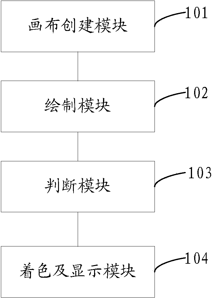
The invention provides a composite buffer area image display method and a composite buffer area image display device. The method comprises the following steps of: when receiving a command for displaying the image of a buffer area, creating a canvas having a transparent channel; drawing each buffer area image on the canvas; obtaining transparence of pixel points in the buffer area images on the canvas, and judging whether the corresponding pixel point belongs to a composite buffer area image according to the transparence; if yes, recoloring the corresponding pixel point according to the transparence and a pre-building color comparison table, and displaying each recolored pixel point. According to the composite buffer area image display method and device, information of the composite buffer area information is prevented from losing, occupation of CPU resources is reduced, and the image displaying efficiency of the composite buffer area is improved.

Description

technical field [0001] The invention relates to the field of image display, in particular to a composite buffer image display method and a composite buffer image display device. Background technique [0002] With the rapid development and maturity of computer technology and surveying and mapping technology, the use of GIS system (Geographic Information System, geographic information system) is becoming more and more common, not only in professional aviation and military fields, but also in the public field. Common, such as map software for various mobile devices. Buffer display is a commonly used function in GIS system, which expresses the degree of external radiation influence of certain GIS system elements. Features include geometric entities such as points, lines, and areas. The area at a certain distance around the geometric entity is the buffer zone of the geometric entity, and it is usually necessary to set a certain color for this buffer zone and display it. [000...

Claims


Application Information

Patent Timeline
IPC IPC(8): G06F3/14G06T1/00
Inventor 陈泓坤
Owner GUANGDONG VTRON TECH CO LTD
Learn More