
Deep plate loading test device

A technology of deep plate load and test device, which is applied in the test of basic structure, construction, basic structure engineering, etc. It can solve the problems of instability, difficult reaction force to meet the test requirements, too long force transmission column, etc., and achieve high accuracy , good promotion and application value, and large loading capacity

Active Publication Date: 2014-10-01
ANHUI GOLDENLAND ARCHITECTURAL DESIGN
View PDF3 Cites 7 Cited by
  • Summary
  • Abstract
  • Description
  • Claims
  • Application Information

AI Technical Summary

Problems solved by technology

In practice, there are still problems with anchor piles or surcharges for deep foundations, and the reaction force they can provide is difficult to meet the test requirements, especially for long piles, there has always been the problem of instability caused by too long force transmission columns

Method used


Image

  • Deep plate loading test device

Examples


Embodiment Construction

[0023] The preferred modes of the present invention will be further described in detail below in conjunction with the accompanying drawings.

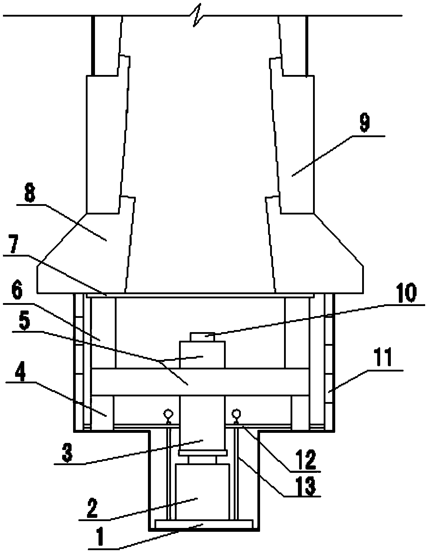
[0024] see figure 1 , the composition of the deep plate load test device is as follows:

[0025] The center of the bearing plate 1 is provided with a jack 2 and a force transmission column 3 successively, and a reference beam 12 is placed outside the force transmission column 3 in a non-contact manner.

[0026] On the same horizontal plane of the benchmark beam 12, there are successively a support 4, a main beam 5, a secondary beam 6, a backing plate 7, a concrete ring beam 8 and a concrete retaining wall 9 on the pile side; wherein, the main beam 5 is cross-shaped, and consists of two cross-stacked The lower surface at the center is connected with the upper surface of the force transmission column 3 in conflict, and the upper surface is equipped with a camera 10 aimed at the dial of the concrete ring beam 8, the dial indicator 13 and ...


PUM


Abstract

The invention discloses a deep plate loading test device which comprises a force transmitting column (3) arranged at the center of a bearing plate (1), and a jack (2) which abuts against and is connected between the bearing plate (1) and the force transmitting column (3). A standard beam (12) is arranged outside the force transmitting column (3) and matched and connected with a dial indicator (13) of the bearing plate (1). A support (4), a main beam (5), an auxiliary beam (6), a base plate (7), a concrete ring beam (8) and a pile side concrete protection wall (9) are sequentially arranged on the same horizontal plane of the standard beam (12). The lower surface of the main beam (5) abuts against and is connected with the upper surface of the force transmitting column (3). The standard beam (12) and the main beam (5) are parallel to the bearing plate (1). The vertical center line of the bearing plate (1), the vertical center line of the jack (2), the vertical center line of the force transmitting column (3) and the vertical center line of the main beam (5) coincide with one another and are perpendicular to the bearing plate (1). The deep plate loading test device is simple in structure and high in loading capacity and can be widely used for deep foundation plate loading tests.

Description

technical field [0001] The invention belongs to the technical field of construction engineering, in particular to a deep plate load test device. Background technique [0002] With the development of construction technology and the modernization of mechanical equipment, in order to adapt to complex geological conditions and environmental conditions, deep pile foundations, as the most commonly used foundation forms for high-rise buildings and large bridges, have been more and more widely used in construction engineering. Pile foundation technology At the same time, its quality inspection has become more and more important, and higher requirements have been put forward for its load test. [0003] The vertical bearing capacity of a single pile is mainly composed of two parts, one is the characteristic value of pile side friction resistance, and the other is the characteristic value of the total end resistance of the bearing layer. It can be seen that determining the bearing capa...

Claims


Application Information

Patent Timeline
Patent Type & Authority Applications(China)
IPC IPC(8): E02D33/00
Inventor 葛凌赵利利王江涛杨成斌何文军张能钦
Owner ANHUI GOLDENLAND ARCHITECTURAL DESIGN
Learn More