
Secondary high-pressure grouting expansion bit anchor rod and construction method thereof

A technology of secondary grouting and enlarged head, which is used in infrastructure engineering, construction, sheet pile walls, etc. The end is not dense and other problems, to achieve the effect of large pull-out force, large pull-out force, and small displacement after tensioning

Active Publication Date: 2014-10-01
成都四海岩土工程有限公司
View PDF7 Cites 15 Cited by
  • Summary
  • Abstract
  • Description
  • Claims
  • Application Information

AI Technical Summary

Problems solved by technology

The disadvantages are: 1. The anchoring force depends on factors such as the length of the anchoring section and the nature of the soil in contact with the anchoring section. If it encounters a special soft soil, the reinforcement effect will not be good; 2. Ordinary high-pressure jet expansion head The anchor has the problem of low cement-soil strength and poor grip between the anchor and the rod; 3. The Xiang-type anchor has poor grip between the anchor and the surrounding soil, and the compressed end is not compact

Method used


Image

  • Secondary high-pressure grouting expansion bit anchor rod and construction method thereof
  • Secondary high-pressure grouting expansion bit anchor rod and construction method thereof
  • Secondary high-pressure grouting expansion bit anchor rod and construction method thereof

Examples


Embodiment Construction

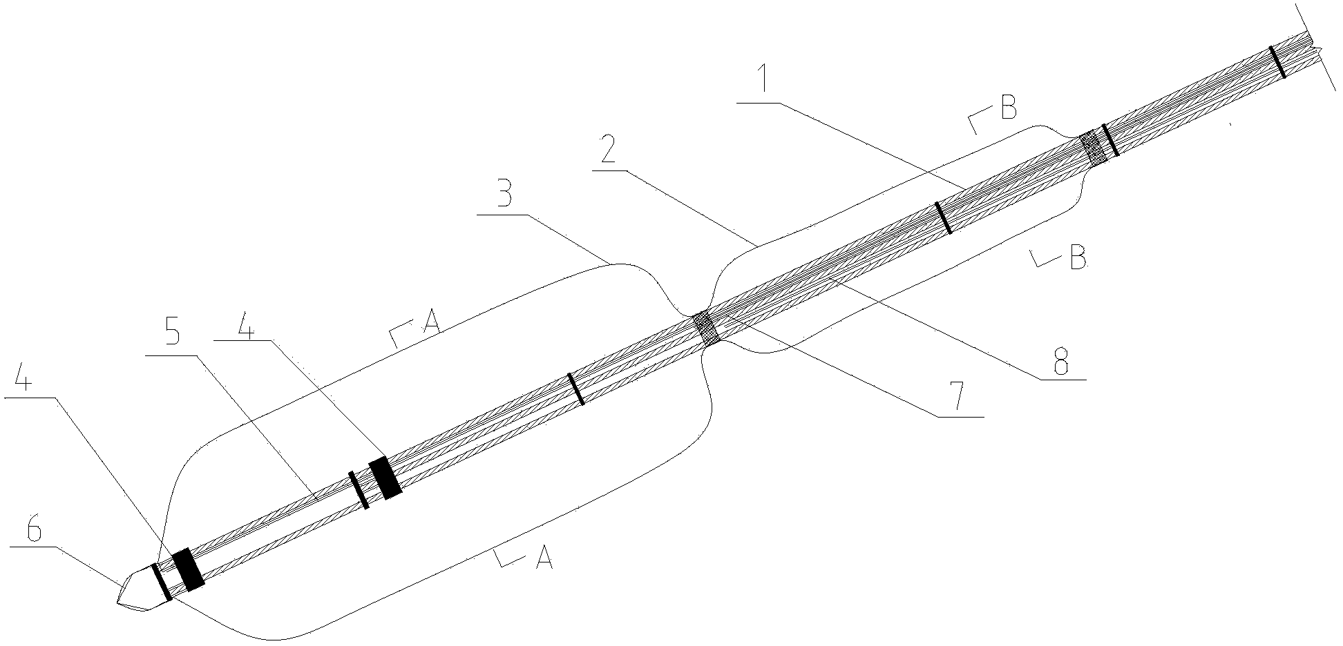
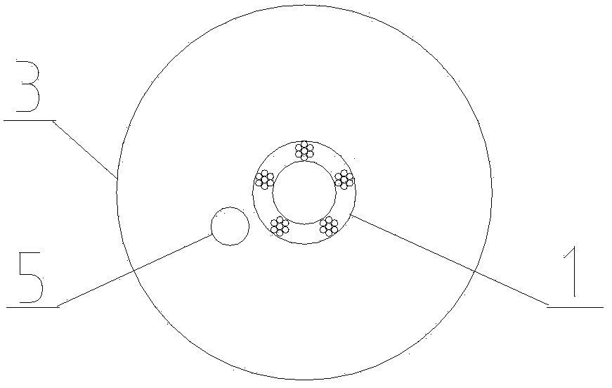
[0025] see Figure 1 to Figure 6 , the present invention includes a bolt body 1, a grouting bag and a grouting pipe, 2 to 3 P anchors 4 are set on the bolt body 1, and a guide cap 6 is installed at the front end of the bolt body to form a pressure dispersion type non-bonding bolt rod body. The key technology is that the centering grouting bag 3 is provided in the front section of the anchor rod body 1, the secondary grouting bag 2 is provided in the rear section of the anchor rod body 1, and the primary grouting pipe 5 and the secondary grouting pipe are arranged on the anchor rod body. 8. The outlet of the primary grouting pipe 5 is located at the front end of the anchor rod body in the centering grouting bag 3 , and the outlet of the secondary grouting pipe 8 is located at the front end of the secondary grouting bag 2 .

[0026] The P anchor 4 is located in the centering grouting bag 3 .

[0027] An exhaust pipe 7 is arranged on the body of the anchor rod, and the outlet o...


PUM


Abstract

The invention discloses a secondary high-pressure grouting expansion bit anchor rod and a construction method of the secondary high-pressure grouting expansion bit anchor rod and belongs to a novel anchoring structure. The secondary high-pressure grouting expansion bit anchor rod comprises an anchor rod body, grouting bags and grouting pipes. The secondary high-pressure grouting expansion bit anchor rod is characterized in that a centering grouting bag is arranged on the front segment of the anchor rod body, a secondary grouting bag is arranged on the rear segment of the anchor rod body, a primary grouting pipe and a secondary grouting pipe are arranged on the anchor rod body, an outlet of the primary grouting pipe is located at the foremost end of the portion, located in the centering grouting bag, of the anchor rod body, and an outlet of the secondary grouting pipe is located at the front end in the secondary grouting bag. The construction method of the secondary high-pressure grouting expansion bit anchor rod comprises the steps of pore forming, rod body placement, grouting of the centering grouting bag, secondary grouting and tensioning for locking. The secondary high-pressure grouting expansion bit anchor rod and the construction method of the secondary high-pressure grouting expansion bit anchor rod have the advantages that after primary grouting and solidification, secondary high pressure is adopted for grouting the secondary grouting bag, and cemented soil on the rear segment of an expansion bit is squeezed closely or cracked by means of high-pressure grouting, so that an anchoring body applies precompression to a soil body, the frictional resistance between the anchoring body and the soil body is enhanced, and consequently the pulling resistance of the anchor rod is increased.

Description

technical field [0001] The invention discloses a secondary high-pressure grouting expansion head anchor rod and a construction method, which belong to a novel anchor structure and its construction method. The anchoring structure widely relates to the fields of foundation pit support, side slope support and foundation anti-floating engineering of construction engineering. Background technique [0002] The existing anchor rods used in underground engineering and slope reinforcement projects mainly rely on the cohesive force and friction force between the anchorage section and the surrounding soil to transmit loads, and belong to frictional anchor rods. Its disadvantages are: 1. The size of the anchoring force depends on the length of the anchoring section and the nature of the soil in contact with the anchoring section. If it encounters special soft soil, the reinforcement effect will not be good; 2. Ordinary high-pressure jet expansion head The anchor has the problems of low...

Claims


Application Information

Patent Timeline
IPC IPC(8): E02D5/74E02D15/04
Inventor 岳大昌李明廖心北吴文学贾欣媛徐继忠
Owner 成都四海岩土工程有限公司
Learn More