
Peeling device

A peeling device, cement curing technology, applied in construction, building maintenance, manufacturing tools, etc., can solve problems such as poor work efficiency, loud beating noise, and damage to mortar.

Inactive Publication Date: 2014-09-24
MARUTAKA IND
View PDF6 Cites 2 Cited by
  • Summary
  • Abstract
  • Description
  • Claims
  • Application Information

AI Technical Summary

Problems solved by technology

However, scraping machines such as small diamond machines and percussion drills vibrate and beat the mortar by feeding compressed air from a compressor, thereby destroying the mortar, so there is a problem of loud beating sound and poor work efficiency
In particular, when the buildings to be constructed operate on a 24-hour system, or hospitals and schools require quietness, the working time is greatly limited due to the noise accompanying the stripping work, so it takes a long time until the stripping work is completed, and Problems such as high labor costs when performing stripping operations
[0003] In the case of these beating / vibrating scraping machines, the beating and vibration are transmitted to the frame, so there is a risk of damage to the frame such as cracks
In addition, in earthquake-resistant reinforcement works, it is necessary to completely remove low-strength mortar to expose only the concrete frame. However, these scraping machines that perform local scraping take a long time to completely remove the mortar, and cannot remove the mortar with high precision. class questions
In addition, when using these scraping machines, there is a problem that the disassembled mortar becomes fine broken pieces, which generates a lot of dust and dust, and deteriorates the working environment.

Method used


Image

  • Peeling device
  • Peeling device
  • Peeling device

Examples


Embodiment Construction

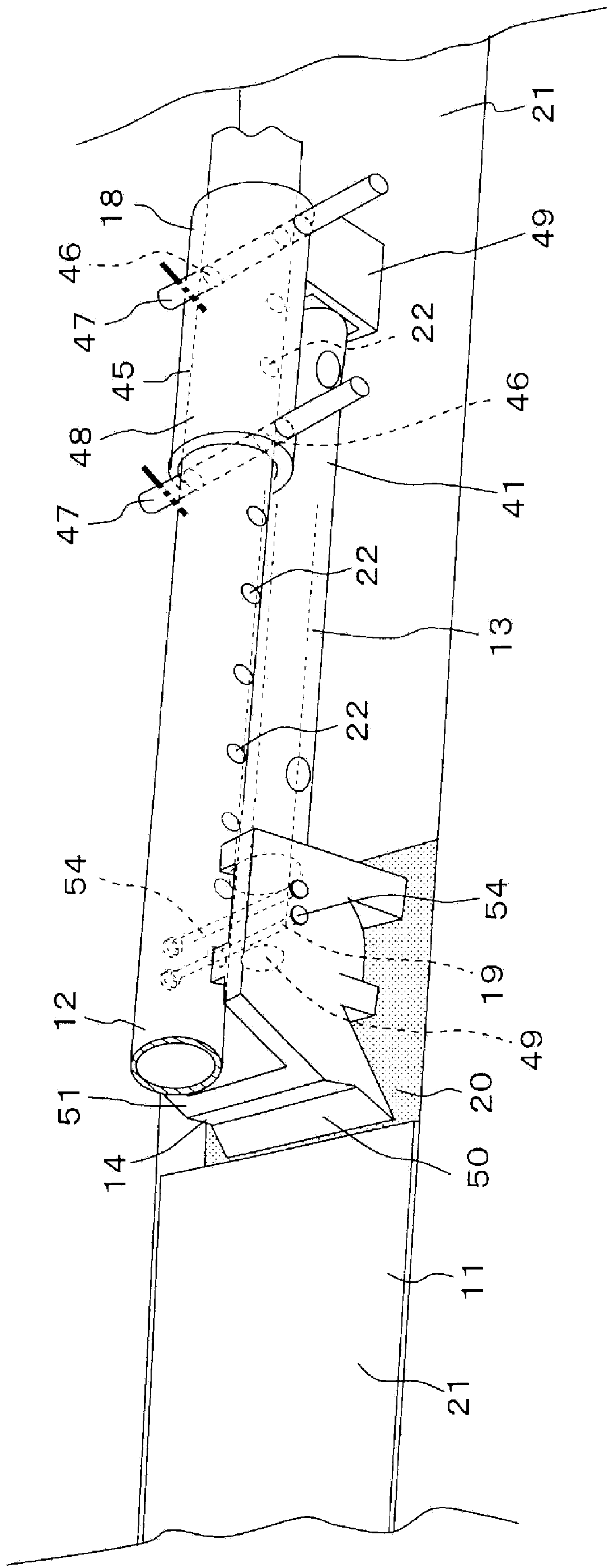
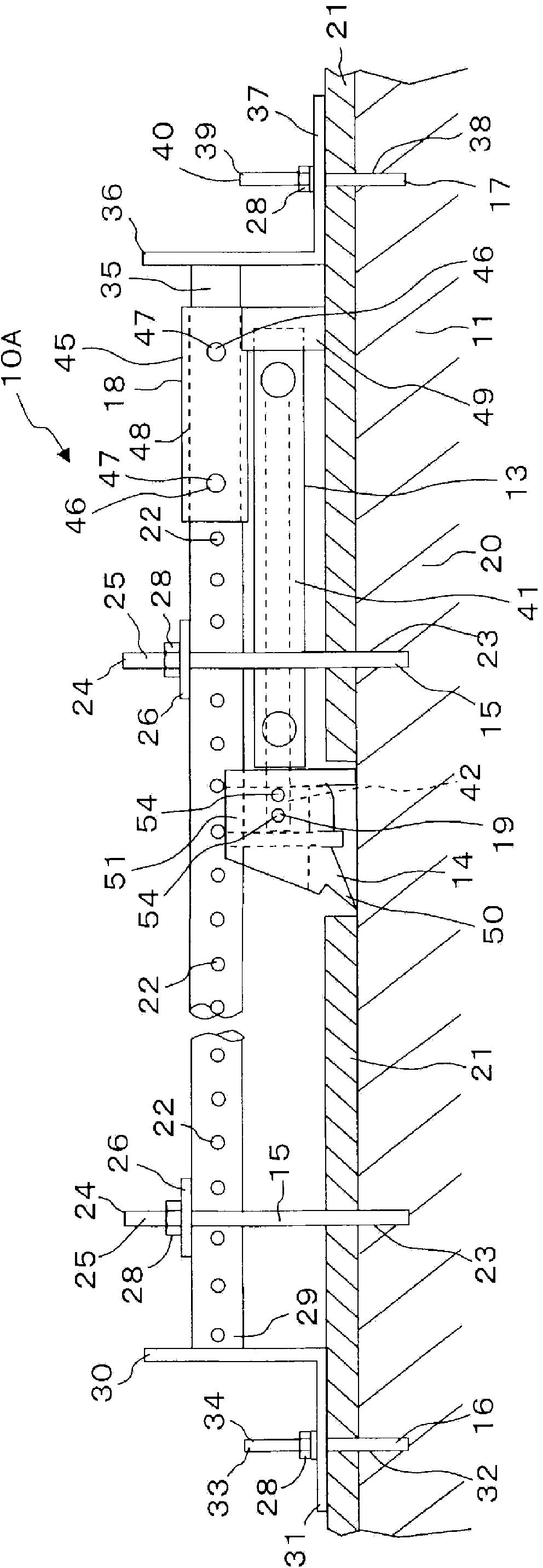
[0058] Referring to the top view of the peeling device 10A shown as an example, that is figure 1 The details of the peeling device according to the present invention will be described as follows with reference to the accompanying drawings. in addition, figure 2 is a perspective view of the peeling device 10A, image 3 is a side view of the peeling device 10A, Figure 4 yes figure 1 L-L line to see the sectional view, Figure 5 It is an enlarged perspective view of the cutter 14. FIG.

[0059] figure 1 In , the single direction is represented by arrow A ( figure 1 In the shown building, it is the front and rear direction), and the arrow B indicates the width direction intersecting with the single direction ( figure 1 The building shown is up and down). Figure 1 ~ Figure 4 In , the peeling apparatus 10A is shown in the state installed in the upper part of the inner wall 11 of a building. figure 2 In , the illustration of the front and rear ends 29, 35 of the guide me...


PUM


Abstract

The invention provides a peeling device capable of keeping sound generated during peeling work to an acceptable level, and that is capable of smoothly peeling mortar from concrete framework. The peeling device (10A) is formed from: a guide member (12) extending in one direction parallel to the outer surface of the mortar (21); a first securing means (15) for preventing movement in the direction away from the outer surface of the mortar (21); a hydraulic jack (13) positioned between the mortar (21) and the guide member (12) and having a piston rod (42) capable of extending in a single direction forward; a first connection means (18) for detachably connecting the jack (13) to the guide member (12); and a cutter (14) positioned at the distal end part of the piston rod (42) and used for peeling mortar (21) from concrete framework (20). In the peeling device (10A), the rod (42) of the jack (13) gradually extends in the single direction forward, and in accompaniment therewith, a blade port (50) of the cutter (14) peels away a predetermined thickness of the mortar (21) from the concrete framework (20) while the cutter (14) gradually advances in the single direction forward.

Description

technical field [0001] The invention relates to a stripping device for stripping cement solidified material laid on a predetermined position of a structure. Background technique [0002] In buildings, the surface of the concrete frame is finished by laying mortar with a predetermined thickness, but after several years, when it is necessary to modify the mortar, seismic reinforcement work by thickening the wall and ceiling, etc., when performing new Before trimming and laying and thickening, the mortar laid on the surface of the concrete frame is stripped. Conventionally, in the mortar stripping work, a small diamond machine and a percussion drill were used to directly scrape the installed mortar by the worker. However, scraping machines such as small diamond machines and impact drills vibrate and beat the mortar by feeding compressed air from a compressor to destroy the mortar. Therefore, there are problems in that the beating sound is loud and the work efficiency is poor. ...

Claims


Application Information

Patent Timeline
Patent Type & Authority Applications(China)
IPC IPC(8): E04G23/02E04F21/00
CPCE04G23/02B28D1/18E04F21/00B28D1/00B28D1/20
Inventor 高木一昌高木荣造朝仓昌志位田达哉
Owner MARUTAKA IND
Learn More