Eureka AIR delivers breakthrough ideas for toughest innovation challenges, trusted by R&D personnel around the world.

Multifunctional horizontal natural gas separation filter

A natural gas, multi-functional technology, applied in the direction of dispersed particle filtration, separation method, dispersed particle separation, etc., it can solve the difficulty in ensuring the latching effect of the latch plate and the locking groove of the blind plate, the difficulty in obtaining the overall matching effect of the blind plate, production and assembly cumbersome and other problems, to achieve the effect of reducing the intensity of cleaning work, shortening the cleaning time, and balancing the effect of latching

Active Publication Date: 2014-09-24
CHANGSHU NO 2 CHEM ENG EQUIP PLANT
View PDF18 Cites 6 Cited by
  • Summary
  • Abstract
  • Description
  • Claims
  • Application Information

AI Technical Summary

Problems solved by technology

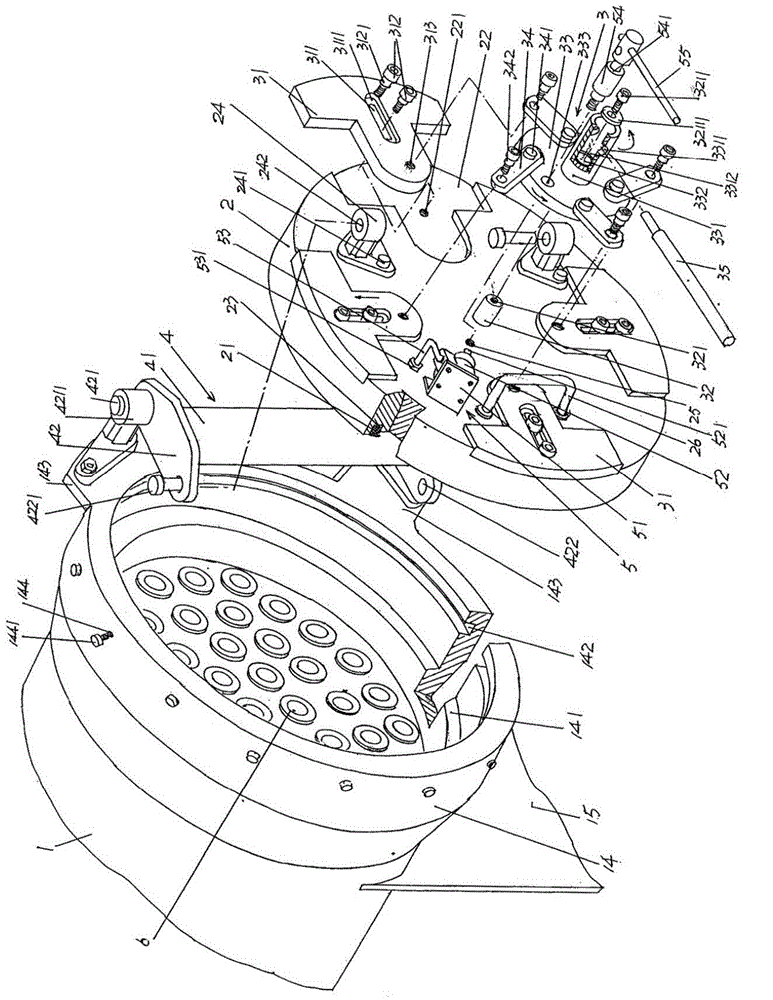
[0008] But the above-mentioned CN101038060A still has the following shortcomings: First, due to the need to independently manufacture a C-shaped conical metal elastic steel ring and a group of latch plates (the patent claims keels, there are seven pieces), and surround a group of latch plates with screw assemblies The circumferential direction of the tapered metal elastic steel ring is fixed one by one, so the production and assembly are relatively cumbersome; second, because the latch plate cooperates with the aforementioned blind plate locking groove, the action of latching or disengaging, that is, the release of latching, depends on the cone shape. The expansion and contraction of the metal elastic steel ring is realized, and because the tapered metal elastic steel ring is fatigued and even deformed after repeated use, it is difficult to guarantee the long-lasting and excellent latching effect of the latch plate and the locking groove of the blind plate; the third , because in a group of latch plates, only two latch plates located at the ports at both ends of the tapered metal elastic steel ring play an active latching role with the locking groove of the blind plate under the thrust of the hinge support, while the rest of the latch plates All of them are passively or passively latched with the blind plate locking groove, so the latching effect of a group of latch plates in the blind plate locking groove is different, which ultimately affects the overall matching effect between the blind plate and the blind plate mating interface. There is a danger of deformation of the blind plate; Fourth, when there is unexhausted natural gas in the cylinder, that is, when there is pressure in the cylinder, if the blind plate is opened rashly for the purpose of maintaining the filter element, there will undoubtedly be undesirable occurrences. Fifth, in order to ensure the cleaning of the blind plate locking groove on the blind plate of the cylinder, so as to obtain the locking effect of the blind plate locking mechanism and it, it is usually necessary to regularly or irregularly check the blind plate locking groove Cleaning, so as to remove the dirt accumulated in the blind plate locking groove, but because there are no structural parts on the blind plate mating interface for cleaning the blind plate locking groove, cleaning is very troublesome, specifically the following four points: One is the lengthy cleaning time, the other is the large consumption of cleaning media such as compressed air or water, the third is the labor intensity of the cleaning personnel, and the fourth is that the cleaning effect is difficult to guarantee

Method used


Image

  • Multifunctional horizontal natural gas separation filter
  • Multifunctional horizontal natural gas separation filter
  • Multifunctional horizontal natural gas separation filter

Examples


Embodiment Construction

[0026] In order to enable the examiners of the patent office, especially the public, to understand the technical essence and beneficial effects of the present invention more clearly, the applicant will describe in detail the following in the form of examples, but none of the descriptions to the examples is an explanation of the solutions of the present invention. Any equivalent transformation made according to the concept of the present invention which is merely formal but not substantive shall be regarded as the scope of the technical solution of the present invention.

[0027] In the following descriptions, all concepts involving up, down, left, right, front and rear directionality (or orientation) are for the position state of the picture being described, and the purpose is to facilitate the public Therefore, it cannot be understood as a special limitation on the technical solution provided by the present invention.

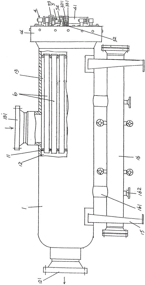
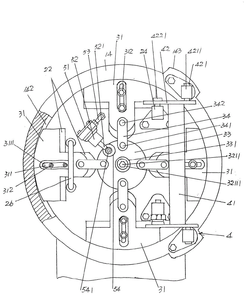
[0028] See figure 1 and figure 2 ,exist figure 2 Th...


PUM


Abstract

The invention discloses a multifunctional horizontal natural gas separation filter belonging to the technical field of filter devices. The multifunctional horizontal natural gas separation filter comprises a cylinder, a blind plate and a blind plate locking mechanism, and is characterized in that latch plate sliding cavities are formed in one side, back on to a separation filter cavity, of the blind plate; the blind plate locking mechanism comprises latch plates, a center disk shaft, a center disk, a traction plate and a center disk operation handle; a center disk sleeve is fixed on one side, back on to the blind plate, of the center disk and is perpendicular to the center disk; a cylinder depressurizing response mechanism is arranged on the wall body of one side, back on to the separation filter cavity, of the blind plate, and is matched with the center disk; a clean hole is formed in the circumferential direction of a blind plate matching opening and in the position corresponding to a blind plate locking groove; a sealing screw is arranged on the clean hole in a matching manner. The multifunctional horizontal natural gas separation filter has the advantages that the structure is simple; the ideal effect of latching all the latch plates and the blind plate locking groove can be enduringly kept; the blind plate is prevented from being deformed; when natural gas exists in the cylinder, the blind plate cannot be opened; the blind plate locking groove can be quickly and conveniently cleaned.

Description

technical field [0001] The invention belongs to the technical field of filter devices, and in particular relates to a multifunctional horizontal natural gas separation filter. Background technique [0002] Since natural gas contains solid particle impurities and trace amounts of liquid, a filter is usually installed on the natural gas transmission pipeline, and the natural gas filtered by the filter can meet the purity requirements, otherwise it will affect the use effect, more precisely, the combustion effect, for example When natural gas is used as a combustion energy source for civil use, if the purity level is insufficient, it is easy to cause clogging of gas appliances and carbon deposits, etc., and when it is used in industrial applications, there is a risk of damage to the burner. [0003] There are two types of natural gas filters, vertical and horizontal. Vertical natural gas filters such as Chinese patents CN2513654Y (natural gas filter), CN2621795Y (multifunctiona...

Claims


Application Information

Patent Timeline
IPC IPC(8): B01D46/00B01D46/42C10L3/10
Inventor 陶金龙王雪良陶怡慧
Owner CHANGSHU NO 2 CHEM ENG EQUIP PLANT
Why Eureka
Eureka Blog
Learn More