
Control timing synchronization method, optical transmission system, and optical transmission apparatus

A technology of timing synchronization and optical transmission, which is applied in the direction of synchronization devices, optical transmission systems, multiplexing system selection devices, etc., and can solve the main signal waiting time and other problems

Active Publication Date: 2014-09-17
FUJITSU LTD
View PDF8 Cites 1 Cited by
  • Summary
  • Abstract
  • Description
  • Claims
  • Application Information

AI Technical Summary

Problems solved by technology

Therefore, there arises a problem that a receiver for the main signal must be prepared in the relay node and a waiting time for transmission of the main signal is required

Method used


Image

  • Control timing synchronization method, optical transmission system, and optical transmission apparatus
  • Control timing synchronization method, optical transmission system, and optical transmission apparatus
  • Control timing synchronization method, optical transmission system, and optical transmission apparatus

Examples


Embodiment Construction

[0023] Embodiments of a control timing synchronization method, an optical transmission system, and an optical transmission device will be described in detail with reference to the accompanying drawings. In describing the embodiments, the same components are given the same reference numerals, and redundant descriptions thereof are omitted.

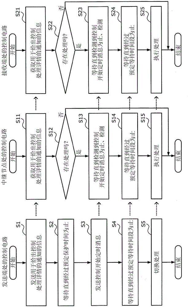
[0024] figure 1 is a diagram of a first example of a method of controlling timing synchronization according to an embodiment. The first example is an example of an optical transmission system in which respective control circuits at the transmission end, relay node, and reception end of a given wavelength path have system clocks that are not synchronized with each other.

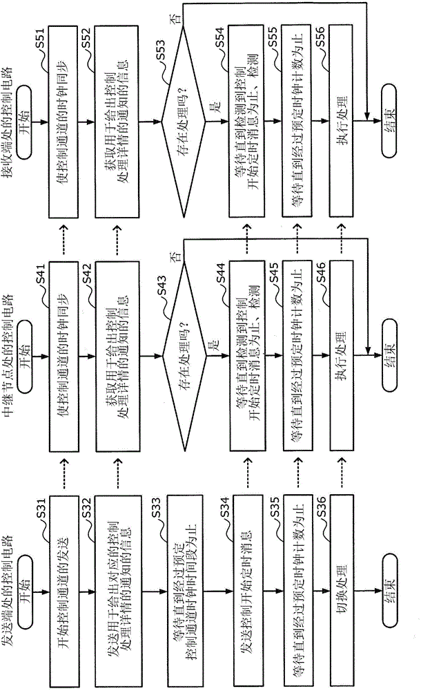
[0025] exist figure 1 , the flowchart on the left represents processing by the control circuit at the transmitting end, the flowchart in the middle represents processing by the control circuit at the relay node, and the flowchart on the right represents processing by the...


PUM


Abstract

A control timing synchronization method is executed by a first and a second optical transmission apparatus. The first optical transmission apparatus: superimposes on a main signal and transmits, information of control process details; waits for a first period; subsequently, superimposes on the main signal and transmits, a message giving notification of control start timing; waits for a second period; and subsequently switches a process of the first optical transmission apparatus to a process corresponding to the control process details. The second optical transmission apparatus: acquires the information on the main signal; waits until detection of the message on the main signal, when a process is present that is to be executed by the second optical transmission apparatus based on the information; waits for the second period when the message is detected while waiting for the detection of the message; and subsequently, executes a process corresponding to the information.

Description

technical field [0001] Embodiments discussed herein relate to control timing synchronization methods, optical transport systems, and optical transport devices. Background technique [0002] Operations of photonic networks may include changing signal wavelengths assigned to wavelength paths; switching modulation / demodulation modes, nonlinear compensation modes, or error correction (forward error correction; FEC (forward error correction)) modes; and reallocating network resources. Since the photonic network is in operation, it is desirable to perform such switching and redistribution with minimal downtime. Therefore, it is necessary to synchronize the switching timings of the respective processes on the transmitting side, the relay node, and the receiving side. [0003] According to the conventional scheme, the control signal channel is allocated to a wavelength other than the wavelength band allocated to the main signal channel, and the main signal channel and the control s...

Claims


Application Information

Patent Timeline
Patent Type & Authority Applications(China)
IPC IPC(8): H04J3/06H04L7/00H04Q11/00
CPCH04L7/0075H04J14/02H04B10/0777H04B10/0779H04B2210/074H04J14/0272H04B10/299H04J2013/0096
Inventor 星田刚司
Owner FUJITSU LTD
Learn More