


Quick Research
Generate reliable direction feasibility study reports for your R&D in just a few steps.

Technical Q&A
Discover and master advanced knowledge NOW. Basics, ideas, possibilities, all at once.

Find Solutions
As an expert in R&D theories, this can generate solutions to your technical problems instantly.

Evaluate Feasibility
Analyze your overall solution with one click, know your potential R&D risks in advance.

Monitor Landscape
Get weekly tech updates, stay abreast of the latest tech innovations and key insights.
OTDR device and method based on coded pulse optical signals
A technology for encoding pulses and optical signals, applied in the direction of using optical devices to transmit sensing components, etc., can solve problems such as higher signal quality requirements, increased dynamic range, and measurement distances that are not as good as large pulse measurement distances, to enrich test functions, improve performance effect
- Summary
- Abstract
- Description
- Claims
- Application Information
AI Technical Summary
Problems solved by technology
Method used
Image

Examples
Embodiment 1
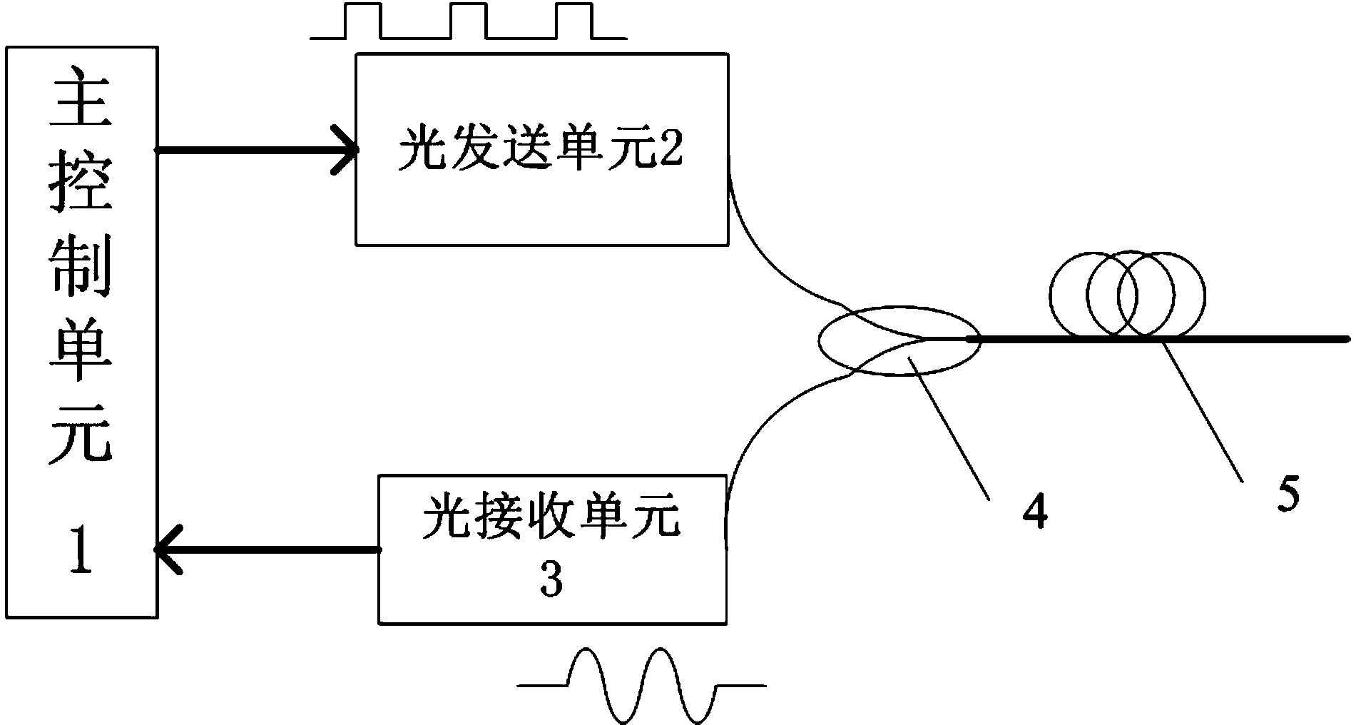
[0059] Such as figure 1 As shown, an OTDR device based on a coded pulsed optical signal is used to detect an event occurring on an optical fiber 5 to be tested, and the OTDR device includes a light emitting unit 2, a light receiving unit 3, a main control unit 1 and a coupling unit 4. The main control unit 1 is connected to the light emitting unit 2 and the light receiving unit 3 respectively.
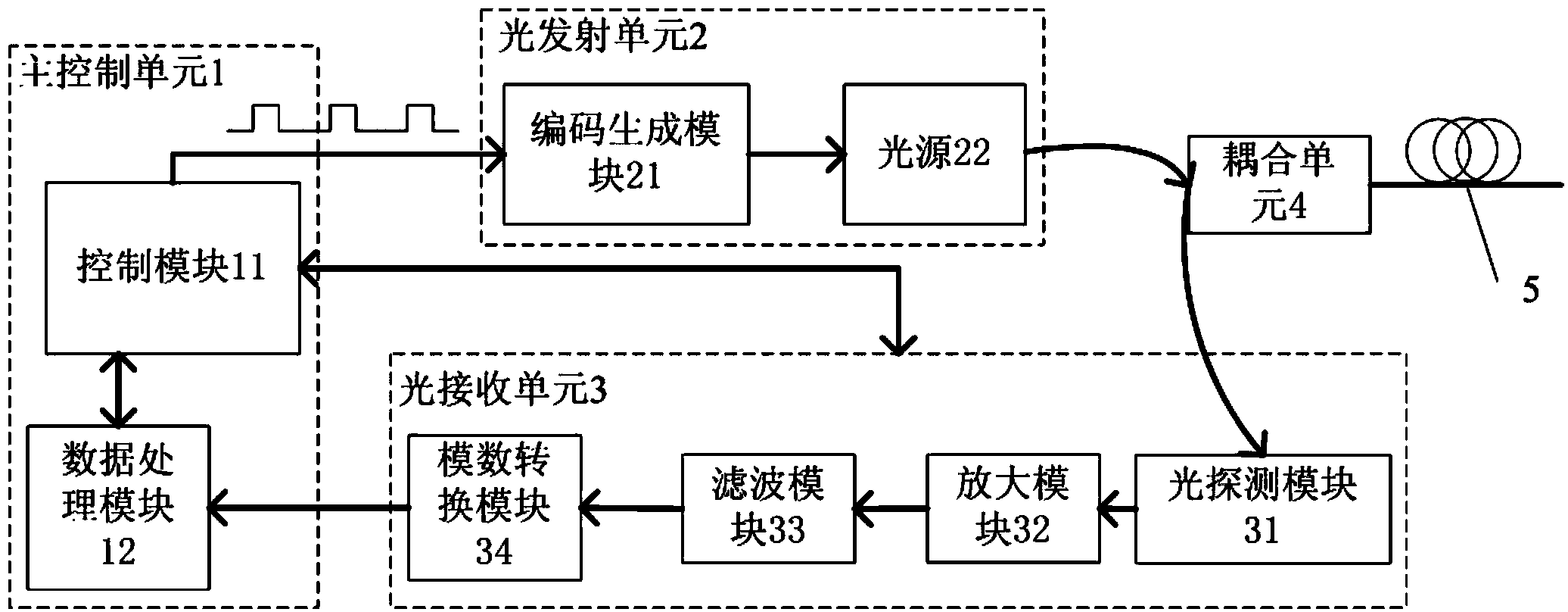
[0060] Such as figure 2 As shown, the light transmitting unit 2 is used to sequentially transmit multiple groups of different types of coded pulsed light signals into the optical fiber 5 to be tested; the coded pulsed light signal refers to the pulsed light signal containing a pseudo-random sequence code. The light emitting unit 2 includes a light source 22 and a code generating module 21. The code generating module 21 is used to generate a driving code, which may be Gray code, and the driving code drives the light source 22 to emit a corresponding coded pulse light signal.
[0061...
Embodiment 2
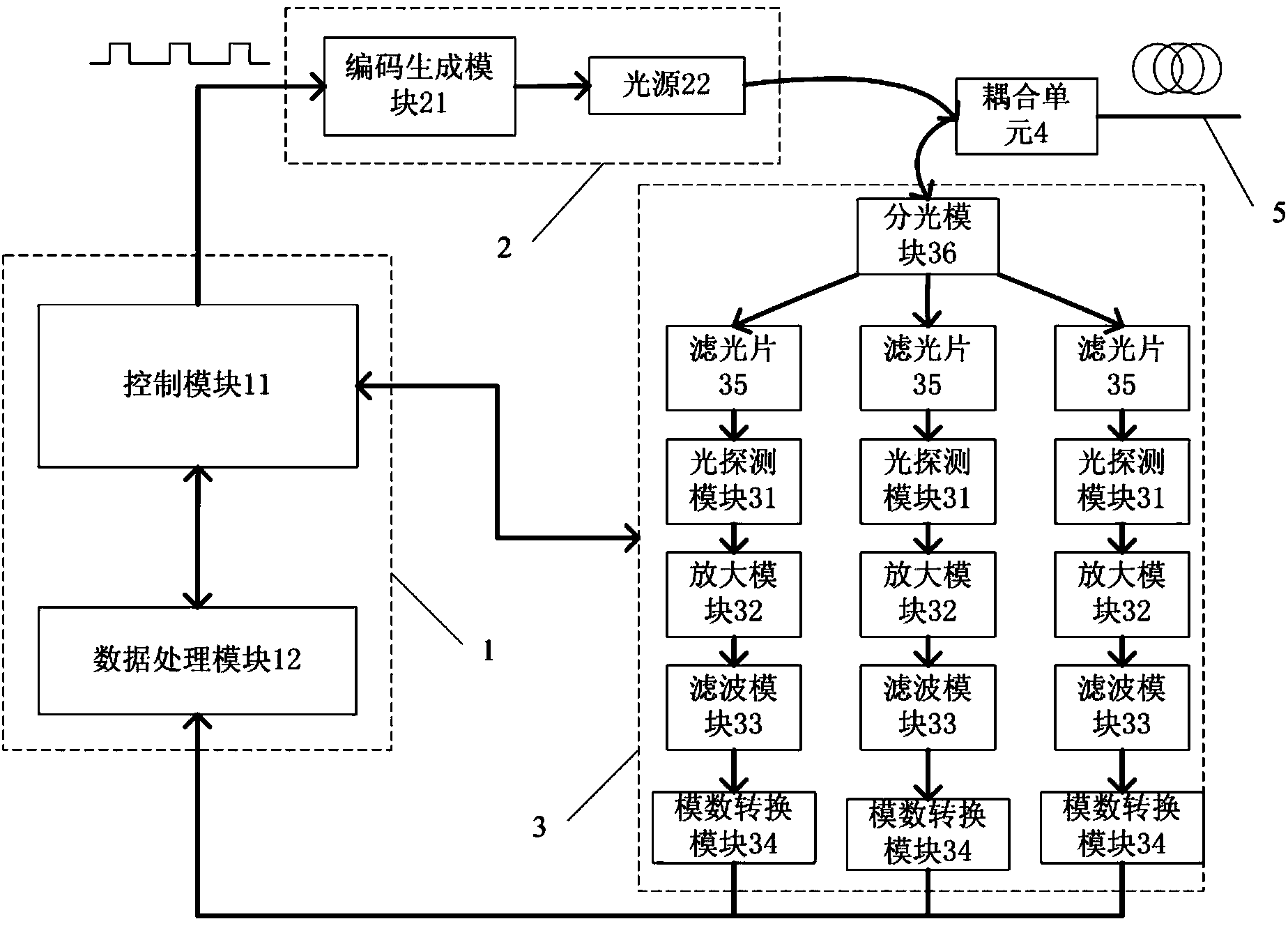
[0115] Such as image 3 As shown, regarding the OTDR device based on the coded pulsed optical signal, the difference between this embodiment and Embodiment 1 is:
[0116] The light receiving unit 3 includes a light splitting module 35 and three light detection modules 31 , the light splitting module 35 divides the backscatter signal into three scattering sub-signals of different wavelength bands, and inputs the scattering sub-signals to the corresponding light detection modules 31 respectively. Wherein, the optical splitting module 35 is an optical splitter.
[0117] In this embodiment, the light receiving unit 3 also includes three groups of sequentially connected amplification modules 32, filter modules 33 and analog-to-digital conversion modules 34; Conversion module 34.
[0118] Similar to Embodiment 1, in this embodiment, a set of optical detection module 31, amplification module 32, filter module 33 and analog-to-digital conversion module 34 can be regarded as one opti...
PUM
 Abstract
Description
Claims
Application Information
 - R&D Engineer
- R&D Manager
- IP Professional
- Industry Leading Data Capabilities
- Powerful AI technology
- Patent DNA Extraction
Browse by: Latest US Patents, China's latest patents, Technical Efficacy Thesaurus, Application Domain, Technology Topic, Popular Technical Reports.
© 2024 PatSnap. All rights reserved.Legal|Privacy policy|Modern Slavery Act Transparency Statement|Sitemap|About US| Contact US: help@patsnap.com