
A linear integral Stirling refrigerator

An integral type, refrigerator technology, applied in the direction of refrigerators, refrigeration and liquefaction, compressors, etc., can solve the problem of short length and achieve the effect of reducing vibration displacement

Active Publication Date: 2016-03-09
CHINA ELECTRONICS TECH GROUP CORP NO 16 INST
View PDF6 Cites 0 Cited by
  • Summary
  • Abstract
  • Description
  • Claims
  • Application Information

AI Technical Summary

Problems solved by technology

[0003] The purpose of the present invention is to solve the application drawbacks of the existing rotary integrated Stirling refrigerators, linear split Stirling refrigerators and linear integrated Stirling refrigerators under rotating conditions, and to provide a linear integrated Stirling refrigerator. Stirling refrigerator, the Stirling refrigerator has the characteristics of symmetrical structure, short length, low vibration and easy rotation

Method used


Image

  • A linear integral Stirling refrigerator
  • A linear integral Stirling refrigerator
  • A linear integral Stirling refrigerator

Examples


Embodiment 1

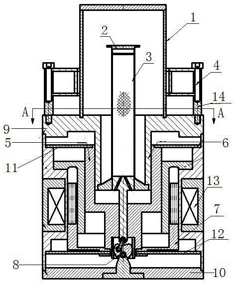
[0025] Such as figure 1 A linear integral Stirling refrigerator shown, including Dewar 1, expander and compressor. The outside of the circumference of the Dewar 1 is provided with a shock absorber 4 for reducing the vibration of the cold head. The expander includes an expansion cylinder 2 and an ejector assembly 3 . The compressor includes a fixed piston 6, a moving cylinder 5, a linear motor and a phase adjustment mechanism 8 for adjusting the movement phase difference between the ejector and the moving cylinder. The fixed piston 6 is a hollow structure, and the expander is located inside the fixed piston 6 . The fixed piston 6 is socketed in the moving cylinder 5, the fixed piston 6 and the moving cylinder 5 have a non-contact gap sealing structure, and the sealed cavity formed by the fixed piston 6 and the moving cylinder 5 is compressed cavity. The moving cylinder 5 reciprocates along its axial direction under the drive of the linear motor. An upper cover 9 is fixed o...

Embodiment 2

[0033] Such as Figure 7 and Figure 8 As shown, the mover assembly 7 is composed of a mover skeleton 72 and a mover winding 73 . The stator assembly 13 is composed of a stator frame 15 , magnetic poles 17 and stator permanent magnets 18 .

[0034] Others are with embodiment 1.

[0035] During operation, the fixed piston 6 is fixed, and the moving cylinder 5 reciprocates along its axial direction under the drive of the linear motor moving subassembly 7 . In the present invention, the expander is placed inside the fixed piston 6, which shortens the overall length of the linear integrated Stirling refrigerator; and by arranging the shock absorber 4 outside the Dewar 1, the vibration displacement at the cold head can be reduced, It is beneficial to the application of the linear Stirling refrigerator on the gyro frame of the missile.


PUM


Abstract

The invention relates to a linear integral stirling cryocooler. The stirling cryocooler comprises a Dewar, an expansion machine and a compressor. The outer side of the circumference of the Dewar is provided with a damper for reducing the vibration of a cold head. The expansion machine comprises an expansion cylinder and a displacer component. The compressor comprises a fixed piston, a movable cylinder, a linear motor and a phase regulation mechanism for regulating the movement phase difference between a displacer and the movable cylinder. The fixed piston is of a hollow structure, and the expansion machine is located in the fixed piston. The fixed piston is sleeved with the movable cylinder, a non-contact clearance sealed structure is arranged between the fixed piston and the movable cylinder, and a sealed cavity formed by the fixed piston and the movable cylinder is a compression cavity. The movable cylinder reciprocates along the axial direction of the linear motor under the driving of the linear motor. According to the technical scheme, by adopting the invention, the length of the integral linear integral stirling cryocooler is shortened, the vibration of the cold head is reduced, and the application of the linear stirling cryocooler to the gyro gimbal of a guided missile is facilitated.

Description

technical field [0001] The invention relates to the technical field of Stirling refrigerators, in particular to a linear integral Stirling refrigerator. Background technique [0002] At present, there are mainly three types of Stirling refrigerators: rotary integral Stirling refrigerators, linear split Stirling refrigerators and linear integral Stirling refrigerators. The rotating integral Stirling refrigerator is driven by a rotating motor and has an "L" shape. Under the rotating condition, not only does it need to increase the counterweight, but the rotating motor will also bring greater radial vibration to the cold head. The linear split Stirling refrigerator is composed of an opposed linear compressor and an expander, connected by branch pipes in the middle, and its shape is "丩" shape. In the linear split Stirling refrigerator, the compressor and the expander need to be placed separately under the rotating condition, which will take up a large space, and the flexibility...

Claims


Application Information

Patent Timeline
Patent Type & Authority Patents(China)
IPC IPC(8): F25B9/14
Inventor 杨坤朱魁章
Owner CHINA ELECTRONICS TECH GROUP CORP NO 16 INST
Learn More