Automatic rubbish compression device of residential rubbish transfer station

A technology of garbage transfer station and pneumatic device, which is applied in the direction of garbage transmission, garbage collection, storage devices, etc., and can solve the problems of time-consuming, labor-intensive and uneconomical

Inactive Publication Date: 2014-09-17
邵珠章
View PDF11 Cites 0 Cited by
  • Summary
  • Abstract
  • Description
  • Claims
  • Application Information

AI Technical Summary

Problems solved by technology

Ordinary communities use garbage trucks to transport garbage to the garbage dump every day, which is time-consuming, laborious, and uneconomical. It is urgent to solve this problem

Method used


Image

  • Automatic rubbish compression device of residential rubbish transfer station
  • Automatic rubbish compression device of residential rubbish transfer station

Examples


Embodiment Construction

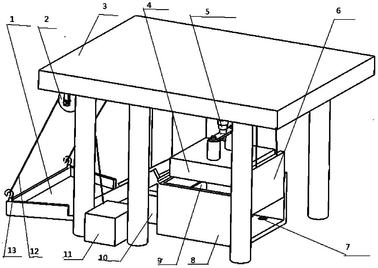
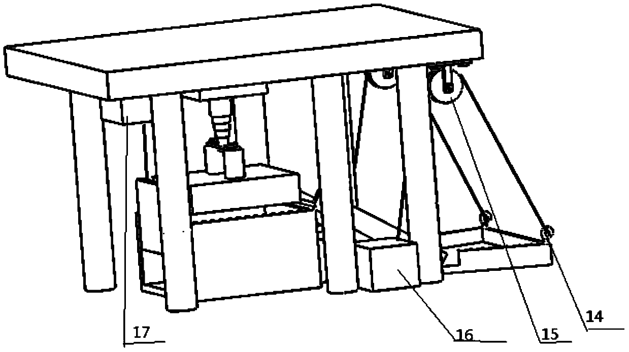
[0010] As shown in the figure, an automatic garbage compression device for a community garbage transfer station is composed of a feed hopper 1, a pulley 2, a basic support 3, a compression plate 4, a first pneumatic device 5, an outlet baffle 6, and a sewage outlet filter device 7. Garbage container 8, push plate 9, second pneumatic device 10, first motor 11, steel rope 12, hook one 13, hook two 14, pulley two 15, second motor 16, third motor 17 Yes, the base support 3 is installed on the ground, and the first hook 13 and the second hook 14 are installed on the feed hopper 1. The first hook 13 and the second hook 14 have steel ropes 12 bypassing the first pulley 2 and the second pulley 15 to connect On the first motor 11 and the second motor 16 shafts, the first motor 11 and the second motor 16 are installed on the ground, the pulley one 2 and the pulley two 15 are installed on the top of the base support 3, and the compression plate 4 is connected under the first pneumatic dev...


PUM


Abstract

The invention provides an automatic rubbish compression device of a residential rubbish transfer station and belongs to the field of municipal facilities. The automatic rubbish compression device is composed of a first motor, a second motor, a third motor, a first pneumatic device, a second pneumatic device, a base support, a feed hopper, a compression plate, a rubbish container, a pushing plate, an outlet baffle, a first pulley, a second pulley, a sewage hole filter unit, steel wire ropes, a first lifting hook and a second lifting hook. The base support is mounted on the ground. The first lifting hook and the second lifting hook are mounted on the feed hopper and connected with the steel wire ropes. The steel wire ropes are connected to a first motor shaft and a second motor shaft respectively. The first motor and the second motor are mounted on the ground. The first pulley and the second pulley are mounted on the base support. The compression plate is connected to the lower portion of the first pneumatic device. A lower bottom plate of the rubbish container is provided with sewage holes. The sewage hole filter unit is arranged on the sewage holes. The outlet baffle connected with the steel wire ropes is arranged at the discharge position of the rubbish container. The third motor is mounted on the base support. The automatic rubbish compression device has the advantage that rubbish can be well collected and compressed.

Description

technical field [0001] The invention relates to an automatic garbage compression device for a garbage transfer station in a residential area, specifically using a first motor, a second motor and a third motor, a first pneumatic device and a second pneumatic device, a basic support, a feeding hopper, and a compression plate , Garbage container, push plate, outlet baffle, etc. constitute an electric compression equipment. Background technique [0002] Garbage compression is one of the necessary steps in modern garbage treatment. After compression, the volume of garbage becomes smaller, which is easy to transport and handle. However, garbage compression is carried out in garbage dumps, and few of them are compressed in residential areas. Ordinary communities use garbage trucks to transport garbage to the garbage dump every day, which is time-consuming, laborious, and uneconomical. It is urgent to solve this problem. Contents of the invention [0003] In view of the above pr...

Claims


Application Information

Patent Timeline
IPC IPC(8): B65F9/00
Inventor 邵珠章张豪金华刘志鹏韩绍峰王心洋曹先锋
Owner 邵珠章
Why Eureka
Try Eureka