Rotor for laboratory centrifuge

A technology of laboratory centrifuges and rotors, which is applied in centrifuges and other directions, and can solve complex and other problems

Active Publication Date: 2014-09-10
SIGMA LABORZENTRIFUGEN
View PDF5 Cites 3 Cited by
  • Summary
  • Abstract
  • Description
  • Claims
  • Application Information

AI Technical Summary

Problems solved by technology

However, obtaining a uniform temperature of the rotor, the centrifuge interior and the material mixture to be treated also requires special measures in terms of construction, which are relatively complex

Method used


Image

  • Rotor for laboratory centrifuge
  • Rotor for laboratory centrifuge
  • Rotor for laboratory centrifuge

Examples


Embodiment Construction

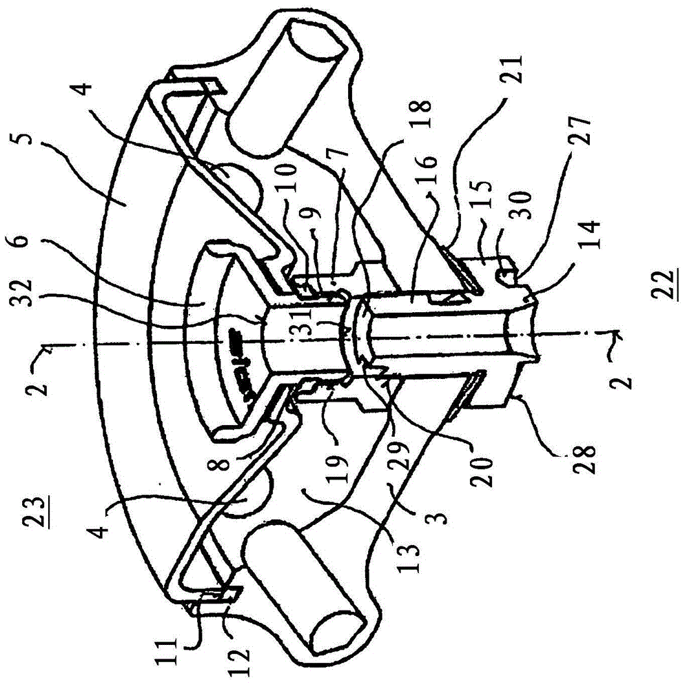
[0017] exist figure 1 and 2 In , the rotor of a laboratory centrifuge, not otherwise indicated with reference numerals, is designated with reference numeral 1 , which rotor has a rotationally symmetrical structure about its axis 2 . The rotor comprises a rotor body 3, in the peripheral region of which is provided a receptacle 4, in a manner known per se, for receiving a container in which there is Processed material mixtures.

[0018] A cover is identified with reference numeral 5 , which covers the rotor body 3 and is screwed via a cover screw 6 extending coaxially to the axis 2 with a nut 7 which is located below the cover 5 . Attached to the cover screw 6 is a hollow cylindrical part 9 with an external thread that extends through the recess 8 of the cover 5 and engages with the internal thread 19 of the nut 7 . A sealing ring 10 , preferably in the form of a four-lip seal, is accommodated between cover 5 and nut 7 , to be precise in annular spaces diametrically opposite ...


PUM


Abstract

A rotor body (3) intended for a laboratory centrifuge is provided with a rotor hub (14) which is inserted in a central opening and on the outside of which at least one helically curved continuous groove (27) runs so as to form a transport facility for cooling air which is effective in the direction of its axis (2) between the upper side (23) and the underside (22) of the rotor (1). In this way, a cooling airstream which runs axially through the rotor (1) and undergoes direct thermal exchange with the rotor (1) and the mixtures to be treated in the laboratory centrifuge can be realized. No additional installation volume is required for this measure and equalization of the temperature of the rotor and the housing accommodating the rotor can be achieved.

Description

technical field [0001] The invention relates to a rotor for a laboratory centrifuge according to the preamble of claim 1 . Background technique [0002] Laboratory centrifuges comprise a housing which can be closed by means of a cover, in which housing a rotor connected to an electric drive is suspended in a vibrating manner. In the area of ​​the circumference, the rotor has a series of receptacles into which containers for the material mixture to be treated by centrifugation can be inserted. The rotor is also equipped with a rotor hub via which the rotor can be plugged onto the drive shaft inside the housing. Depending on the chemical-physical properties of the material mixture, the centrifugation usually takes place under certain thermal conditions, so that a corresponding air conditioning of the rotor or the housing interior is necessary. It is known to equip the centrifuge, ie its housing, with a corresponding heating and / or cooling system, in particular with a coolant...

Claims


Application Information

Patent Timeline
Patent Type & Authority Applications(China)
IPC IPC(8): B04B5/04B04B15/02B04B7/02
CPCB04B5/0414B04B7/08B04B2009/085B04B7/02B04B2007/025B04B15/02
Inventor E·托特伯格M·比特纳
Owner SIGMA LABORZENTRIFUGEN
Why Eureka
Try Eureka