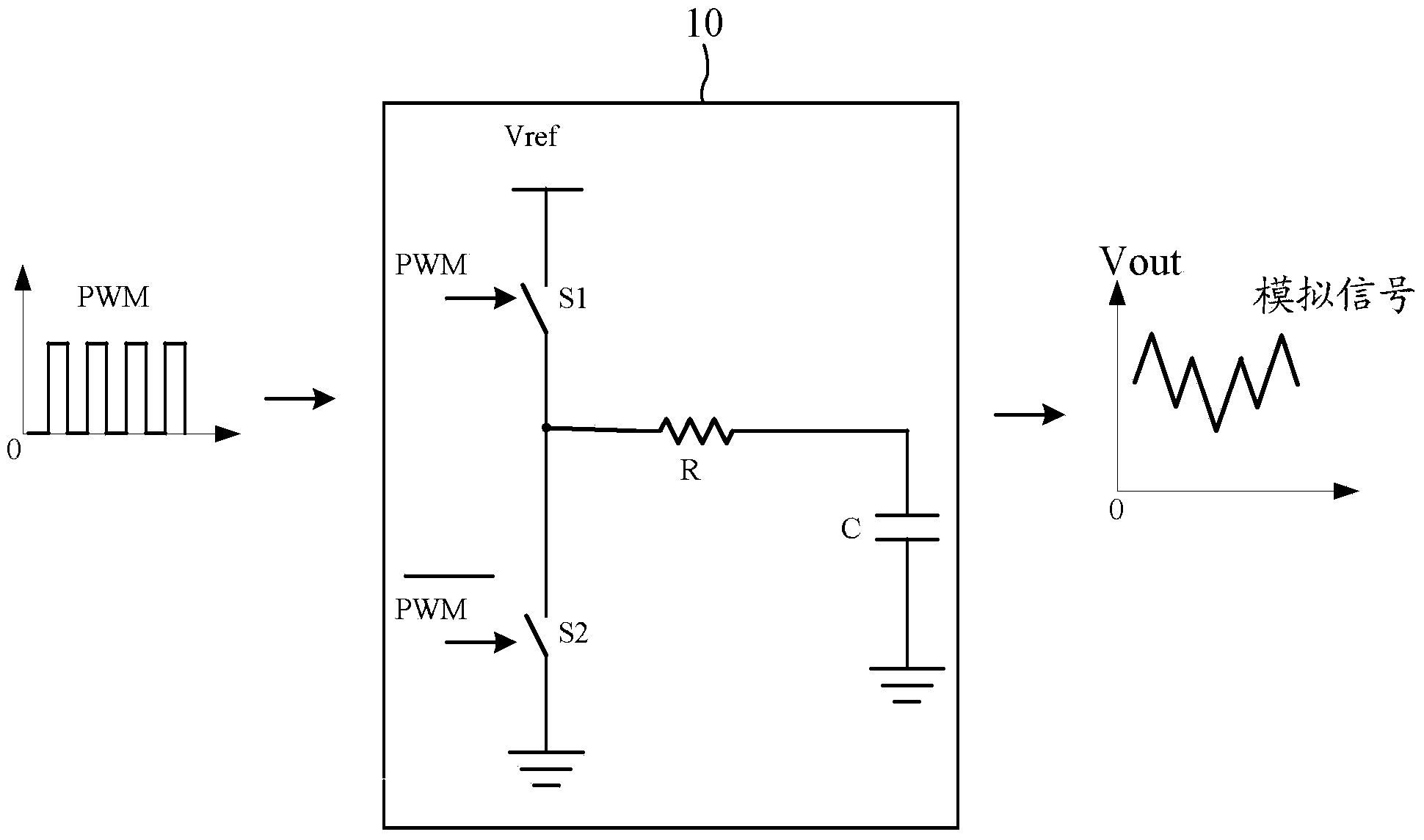
Duty cycle conversion circuit and method
A conversion circuit and duty cycle technology, applied in the direction of output power conversion devices, electrical components, etc., can solve the problems of large output ripple, reduced service life of the conversion circuit, slow response speed of the conversion circuit, etc., to achieve fast response speed, The effect of improving the service life
- Summary
- Abstract
- Description
- Claims
- Application Information
AI Technical Summary
Problems solved by technology
Method used
Image
Examples
Embodiment 1
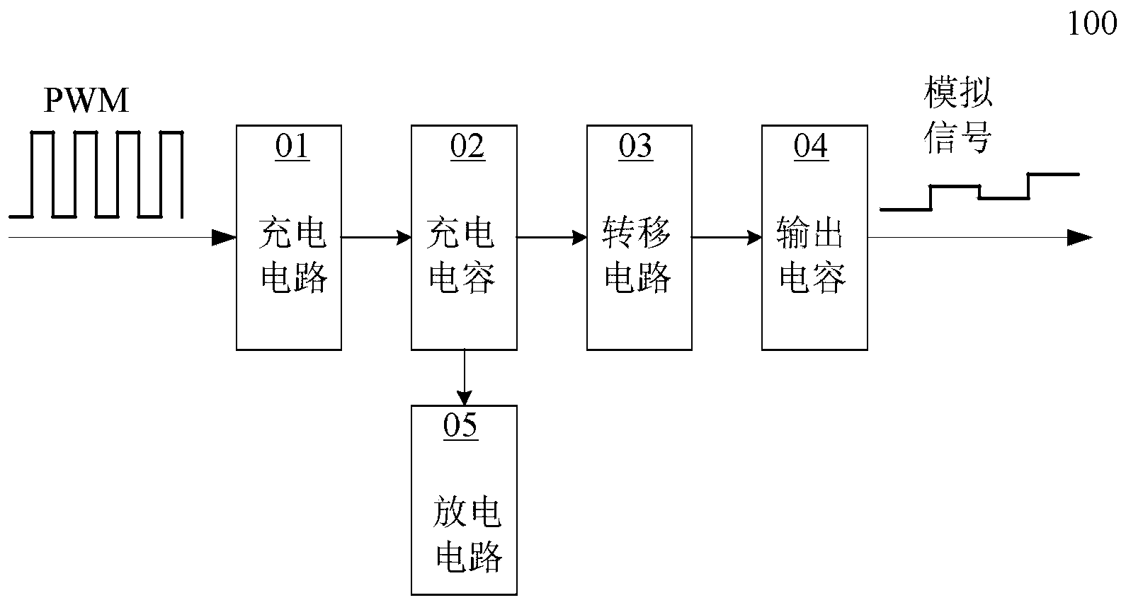
[0041] Please refer to figure 2 , in this embodiment, a duty cycle conversion circuit 100 is proposed for converting a PWM signal into an analog signal. Specifically, the duty ratio conversion circuit 100 includes a charging circuit 01 , a charging capacitor 02 , a transfer circuit 03 , an output capacitor 04 and a discharging circuit 05 .
[0042] In each cycle of the PWM signal, when the PWM signal is at a high level, the charging circuit 01 outputs a charging current to charge the charging capacitor 02;
[0043] When the PWM signal is at low level, the charging current stops charging the charging capacitor 02, and within the transfer time period, the voltage on the charging capacitor 02 is output to the output capacitor through the transfer circuit 03 04 ; during the discharge time period, the charging capacitor 02 is discharged through the discharging circuit 05 to reduce the voltage on the charging capacitor 02 to an initial voltage. The initial voltage here refers to ...
Embodiment 2
[0048] Please refer to image 3 , in this embodiment, an optimized duty ratio conversion circuit 200 of Embodiment 1 is proposed. Specifically, the charging circuit 01 includes a controlled current source A, and the specific controlled current source A is a voltage-controlled current source controlled by a PWM signal. When the PWM signal is at a high level, a voltage V PWM Controlling the controlled current source A to output a charging current I to the charging capacitor 02 1 , when the PWM signal is low, there is no voltage V PWM Control the controlled current source A, then the controlled current source A has no charging current I 1 output.
[0049] In order to ensure the stability and accuracy of the charging process, the charging circuit of this embodiment further includes a charging control switch connected in series with the controlled current source A. Specifically, the charging control switch described in this embodiment includes a charging control switch S1, and ...
Embodiment 3
[0059] In this embodiment, another optimized duty cycle conversion circuit 300 of Embodiment 1 is proposed. For details, please refer to Figure 4 The only difference between this embodiment and the second embodiment is the composition of the charging circuit 01 , and the other parts are the same as those of the second embodiment, and will not be repeated here. In this embodiment, the charging circuit 01 includes a current source and a charging control switch. The specific current source can be a constant current source or any other current source. In this embodiment, the current source is Constant current source A, used to output constant charging current I 1 The charging control switch includes a charging control switch S1, one end of the charging control switch S1 is connected to the constant current source A, and the other end is connected to the charging capacitor O2, and the on and off of the charging control switch S1 is controlled by the PWM signal. When the PWM signa...
PUM
 Abstract
Description
Claims
Application Information
 - Generate Ideas
- Intellectual Property
- Life Sciences
- Materials
- Tech Scout
- Unparalleled Data Quality
- Higher Quality Content
- 60% Fewer Hallucinations
Browse by: Latest US Patents, China's latest patents, Technical Efficacy Thesaurus, Application Domain, Technology Topic, Popular Technical Reports.
© 2025 PatSnap. All rights reserved.Legal|Privacy policy|Modern Slavery Act Transparency Statement|Sitemap|About US| Contact US: help@patsnap.com


