Rotor winding method using automatic rotor winding machine

A winding method and a technology for a winding machine, which are applied in the field of winding machines, can solve the problems of increased production cost, waste of wire raw materials, and high labor intensity, and achieve the effects of cost saving and reliable hooking.

Active Publication Date: 2016-05-11
浙江薪人机电科技有限公司
View PDF4 Cites 0 Cited by
  • Summary
  • Abstract
  • Description
  • Claims
  • Application Information

AI Technical Summary

Problems solved by technology

There are many deficiencies in the rotor coil wound by this manual-assisted semi-automatic method. To wind a groove, it is necessary to wind a circle around the "α" shape at the neck and cut off the thread hooked on the false hook, resulting in a The waste of raw materials increases the production cost a lot
In addition, the winding process is complicated, the labor intensity is high, it is difficult to ensure the stability and consistency of the winding quality, the production efficiency is low, and the production cost will also increase.

Method used


Image

  • Rotor winding method using automatic rotor winding machine
  • Rotor winding method using automatic rotor winding machine
  • Rotor winding method using automatic rotor winding machine

Examples


Embodiment Construction

[0023] The technical solutions of the present invention will be clearly and completely described below through specific embodiments in conjunction with the accompanying drawings.

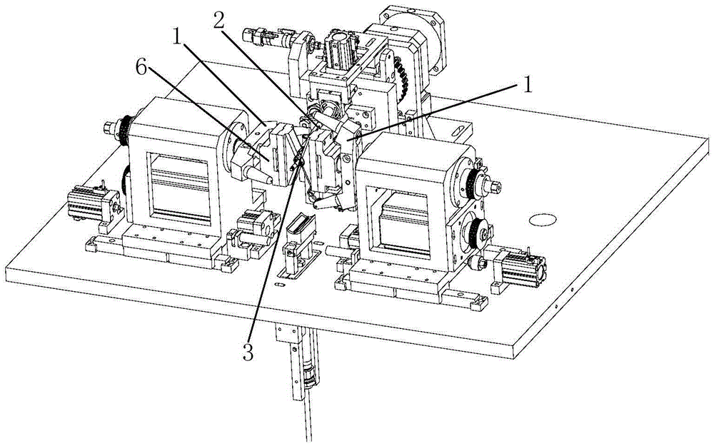
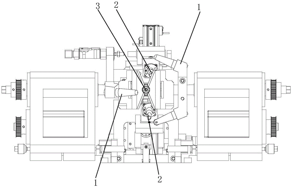
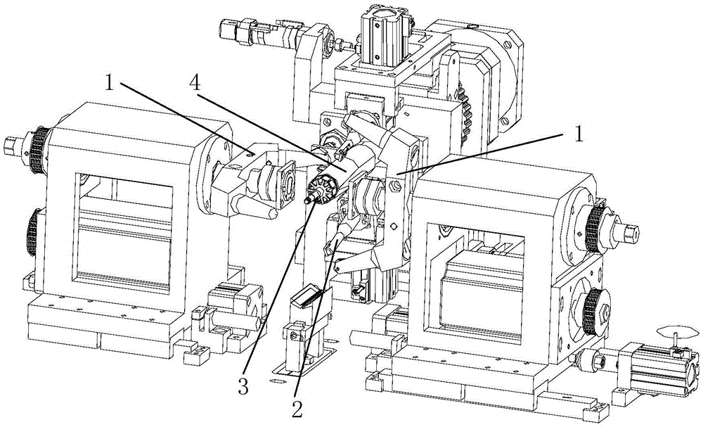
[0024] Please refer to figure 1 , figure 2 and image 3 , figure 1 It is an automatic rotor winding machine during winding according to an embodiment of the present invention, figure 2 yes figure 1 The front view of the automatic rotor winding machine, image 3 It is an automatic rotor winding machine that removes the clamping parts and the inner sleeve. The automatic rotor winding machine specifically includes: two winding fly forks 1, two wire clamps 2, and the rotor 3 is fixed on the indexing of the winding machine. On the main shaft, the inner sleeve 7 (please refer to Figure 4 ) is fixed on the inner rod of the indexing spindle, the outer sleeve 4 is set on the outside of the inner sleeve 7, the positions of the inner sleeve and the inner rod of the indexing spindle are fixed, and the ...


PUM


Abstract

A method for wrapping wires on rotors by using an automatic rotor wire wrapping machine comprises the following specific steps of initializing the automatic rotor wire wrapping machine; wrapping the wires on a first hook of a rotor reverser by matching fly forks, an inner sleeve and an outer sleeve; forwards rotating a rotor to a first groove wire wrapping position corresponding to the first hook and wrapping a wire on the rotor; reversely rotating the rotor so that the wire is broken by a wire clamp after wire wrapping at the first groove wire wrapping position is finished; rotating the rotor to a position corresponding to a second hook; wrapping the wire to the second hook of the rotor by using the inner sleeve and the outer sleeve; wrapping the wire at a second groove wire wrapping position; adjusting the tilt angles of the wire wrapping fly forks, the rotating angle of the rotor and the left-right movement of the wire clamp so that the wire can be clamped or broken by the wire clamp after the wire wraps all the groove wire wrapping positions of the rotor; and releasing the rotor so that the wire wrapping fly forks return to a zero point. The wire wraps on the rotor symmetrically by using the two wire wrapping fly forks, the wrapping wire is distributed symmetrically, the wire is easily hooked, and the production cost is low.

Description

technical field [0001] The invention relates to a winding machine, in particular to a rotor winding method using an automatic rotor winding machine. Background technique [0002] In the prior art, the winding of wires into the grooves of the rotor core is mostly done in a semi-automatic way by manual operation using false hooks. In this way, when winding, manually place the wire hook on the false hook and fold it back around the neck in an "α" shape, and then continue winding. Every time a groove is wound, it must be wound around the neck "α" " form a circle. After the winding is completed, the excess wire head and wire tail are cut off, and then spot welding is used to conduct the coil and the commutator. There are many deficiencies in the rotor coil wound by this manual-assisted semi-automatic method. To wind a groove, it is necessary to wind a circle around the "α" shape at the neck and cut off the thread hooked on the false hook, resulting in a The waste of raw materi...

Claims


Application Information

Patent Timeline
Patent Type & Authority Patents(China)
IPC IPC(8): H02K15/09
Inventor 朱武军郑灿根秦进飞
Owner 浙江薪人机电科技有限公司
Why Eureka
Try Eureka