
Curved display panel and curved display device

A curved surface display and panel technology, applied in the direction of static indicators, nonlinear optics, instruments, etc., can solve the problems of uneven display brightness of scanning lines, image signal distortion, etc., to avoid uneven display brightness, reduce area, and avoid image The effect of signal distortion

Inactive Publication Date: 2014-09-10
TCL CHINA STAR OPTOELECTRONICS TECH CO LTD
View PDF6 Cites 13 Cited by
  • Summary
  • Abstract
  • Description
  • Claims
  • Application Information

AI Technical Summary

Problems solved by technology

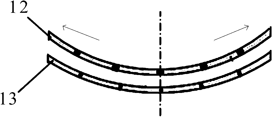
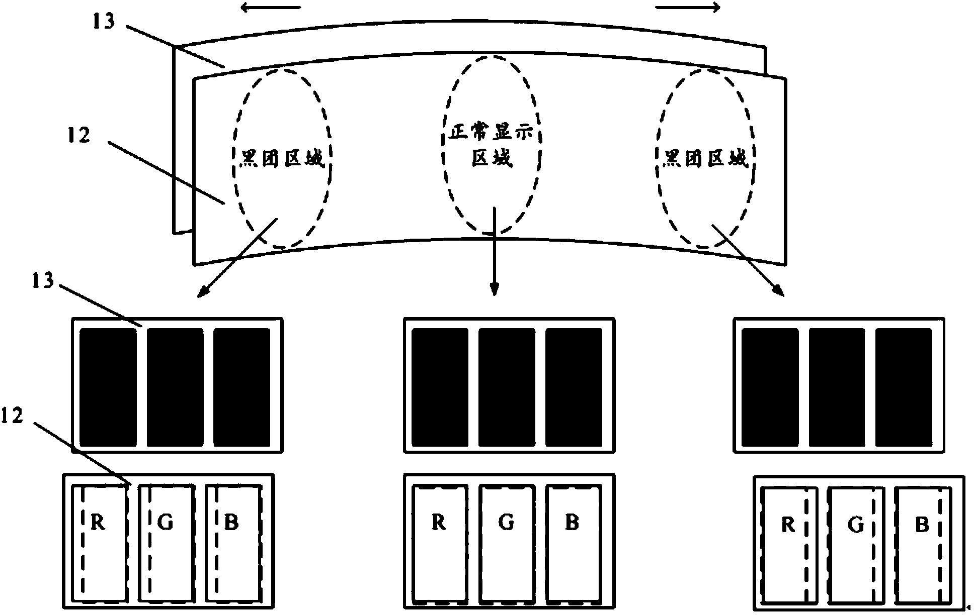
[0005] The object of the present invention is to provide a curved display panel and a curved display device, which can reduce the obvious black clusters and color shifts in the left and right regions of the display panel, thereby increasing the aperture ratio and avoiding serious signal attenuation at the end of the data line. Image signal distortion, and avoid the problem of uneven display brightness caused by insufficient charging of scanning lines

Method used


Image

  • Curved display panel and curved display device
  • Curved display panel and curved display device
  • Curved display panel and curved display device

Examples


Embodiment Construction

[0031] Referring to the drawings, wherein like reference numerals represent like components, the principles of the present invention are exemplified when implemented in a suitable computing environment. The following description is based on illustrated specific embodiments of the invention, which should not be construed as limiting other specific embodiments of the invention not described in detail herein.

[0032] Please refer to figure 2 , figure 2 It is a schematic structural diagram of the curved display panel 200 provided by the present invention. The curved display panel 200 includes a pixel structure disposed in the curved display panel 200, a data line 201 providing a data signal to the pixel structure, and a scanning line 202 providing a switching control signal to the pixel structure;

[0033] The four frames of the curved display panel 200 are composed of two first frames 200a and two second frames 200b, the first frame 200a is adjacent to the second frame 200b,...


PUM


Abstract

An embodiment of the invention discloses a curved display panel and a curved display device. The curved display panel and the curved display device have the advantages that two data driving circuits of the curved display panel simultaneously drive the same data line, and two scanning driving circuits simultaneously drive the same scanning line, so that image signal distortion due to serious signal attenuation at the tail end of the data line can be prevented, and the problem of uneven display brightness of an existing scanning line due to insufficient charging can be solved; long sides of each sub-pixel are parallel to long frames of the curved display panel, short sides of each sub-pixel are parallel to short frames of the curved display panel, accordingly, the areas of black cluster regions on two sides of the curved display panel can be greatly reduced, color cast of a left region and a right region of the curved display panel can be relieved, and the problem of uneven pictures displayed by an existing curved display panel can be solved.

Description

【Technical field】 [0001] The present invention relates to the technical field of display panels, in particular to a curved display panel and a curved display device. 【Background technique】 [0002] In the field of Curved Thin Film Transistor-Liquid Crystal Display (TFT-LCD, Thin Film Transistor-Liquid Crystal Display), usually, the grid (Gate) scanning line 101 is parallel to the long side 100a of the curved display (ie parallel to curved surface arc), and the data (Data) line 102 is perpendicular to the long side 100a of the curved surface display panel, and the long side 11a of each pixel (Pixel) 11 is perpendicular to the long side 100a of the curved surface display panel (that is, each pixel 11 is vertically arranged ), refer to Figure 1a , Figure 1a Taking one pixel 11 as an example, the pixel structure of the existing curved TFT-LCD is illustrated, wherein 100b is the short side of the curved display panel, and 11b is the short side of the pixel. [0003] Since the ...

Claims


Application Information

Patent Timeline
Patent Type & Authority Applications(China)
IPC IPC(8): G02F1/1362G02F1/13
CPCG09G2310/0281G09G2320/0223G09G3/3677G09G3/3688G09G2300/04G09G2320/0233G02F1/1345G09G3/03G02F1/1337G02F1/133G02F1/1333G09G3/3607G09G2300/0452G09G2320/0242G09G2360/06
Inventor 陈政鸿罗时勋吴川
Owner TCL CHINA STAR OPTOELECTRONICS TECH CO LTD
Learn More