
Hole digging and soil picking up device

A technology of borrowing device and locking device, which is applied to manual excavators/dredgers, etc., can solve the problems of poor adaptability, easy tilting, troublesome cost, etc., and achieve the effect of balanced and stable force

Active Publication Date: 2014-09-10
湖南终南山科技发展有限公司
View PDF5 Cites 6 Cited by
  • Summary
  • Abstract
  • Description
  • Claims
  • Application Information

AI Technical Summary

Problems solved by technology

[0002] At present, the commonly used artificial drilling tools in China are hoes, shovels, Luoyang shovels, etc. As we all know, for direct buried electric poles or light poles, the smaller the diameter of artificial drilling, the smaller the damage to the old soil around the hole , the more stable the electric pole or light pole is installed, the better the force, but the hole diameter cannot be controlled by using tools such as hoes and shovels. For example, for a light pole with a diameter of 200mm, the required opening diameter (diameter) is 300mm. When manually using tools such as hoe and shovel, the aperture (diameter) will be enlarged to 500mm, or even 600mm or larger, which will seriously damage the solid old soil around the hole, making the power pole or light pole installed. Poor, easy to tilt; and for small but deep holes, the commonly used manual drilling tools in China are also difficult to operate. Due to the small aperture (diameter), large soil tools cannot be put down. Even with a Luoyang shovel, it is difficult to remove when the soil is dry and hard and non-cohesive, and tools need to be replaced frequently when opening holes, which greatly improves work efficiency. Decrease; the tools used in daily life are only suitable for the situation where the hole diameter is large and the hole size is not high, the adaptability is poor, and it is very troublesome and costly to equip a set of hole opening tools

Method used


Image

  • Hole digging and soil picking up device
  • Hole digging and soil picking up device
  • Hole digging and soil picking up device

Examples


Embodiment Construction

[0031] In order to make the object, technical solution and advantages of the present invention clearer, the present invention will be further described in detail below in conjunction with the accompanying drawings and embodiments. It should be understood that the specific embodiments described here are only used to explain the present invention, not to limit the present invention.

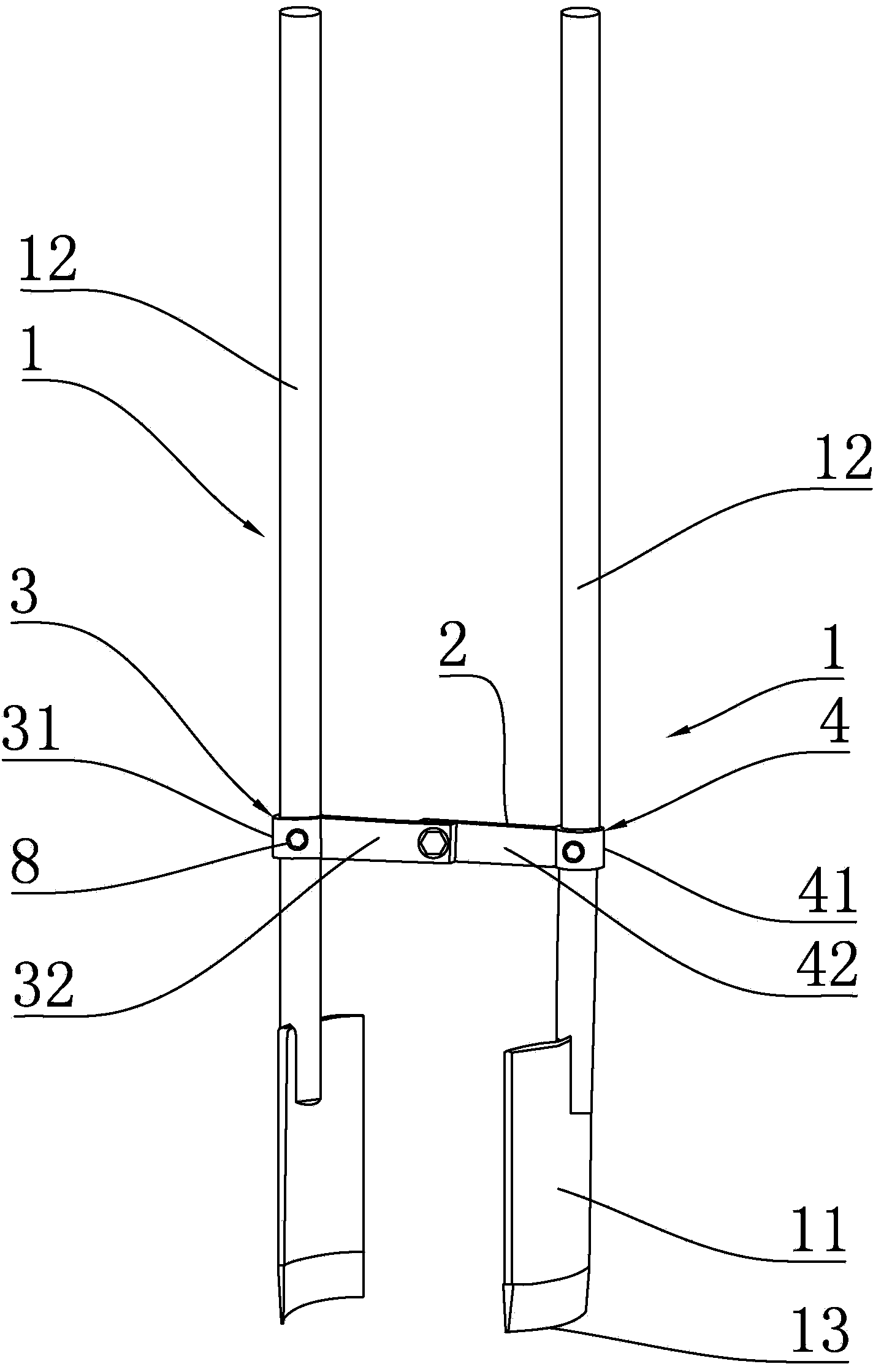
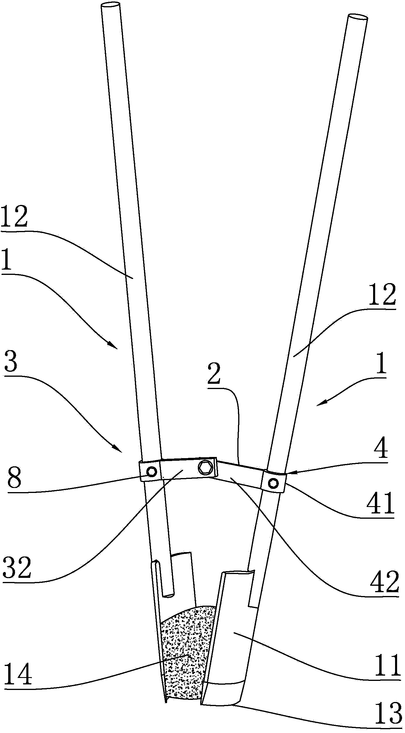
[0032] The invention discloses a hole-boring soil-taking device, figure 1 It is a schematic diagram of the opening state of the opening soil extraction device in the first embodiment of the present invention; figure 2 for figure 1Schematic diagram of the soil fetching state of the center hole soil fetching device.

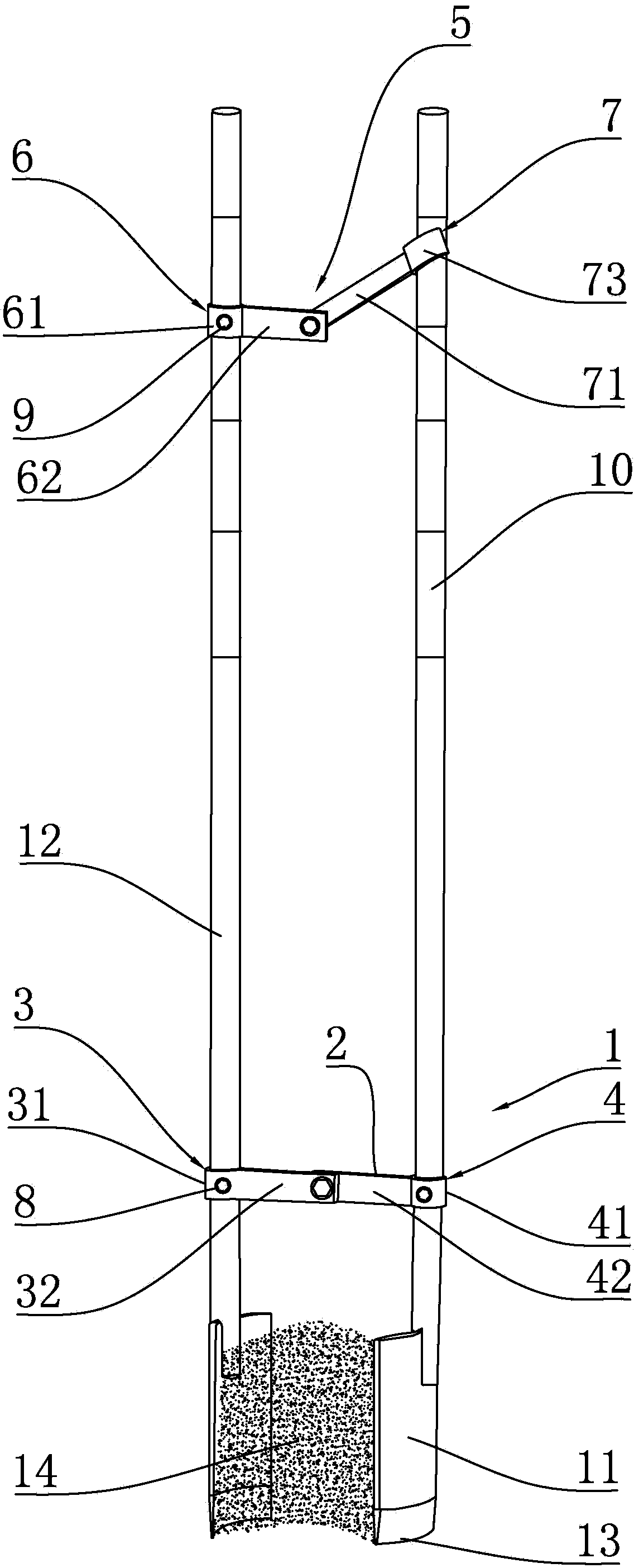
[0033] like figure 1 and figure 2 Shown, a kind of perforating earth taking device comprises two groups of perforating parts 1, namely the first group of perforating parts (the perforating part on the left in the figure) and the second group of perforating parts (the perforating p...


PUM


Abstract

The invention provides a hole digging and soil picking up device which comprises two hole digging pieces and a connecting device through which the two hole digging pieces are connected. Each hole digging piece comprises a shovel piece and a handle connected with the shovel piece. The connecting device comprises a first connecting piece and a second connecting piece which are hinged together, wherein the first connecting piece is fixedly connected with the handle in one hole digging piece, and the second connecting piece is fixedly connected with handle in the other hole digging piece. The hole digging and soil picking up device further comprises a locking device, wherein the locking device comprises a third connecting piece and a fourth connecting piece which are hinged together. By means of the device, deep holes can be dug precisely and soil can be picked up without damaging the pore diameter and the structure of surrounding earth blocks, the device meets the requirement for digging underground holes with various pore diameters and various depths, tools do not need to be frequently replaced when deep holes are dug or soil is picked up, and efficiency of hole digging work is improved.

Description

technical field [0001] The invention belongs to the field of solar street lamp assembly, and in particular relates to a hole-boring soil-taking device. Background technique [0002] At present, the commonly used artificial drilling tools in China are hoes, shovels, Luoyang shovels, etc. As we all know, for direct buried electric poles or light poles, the smaller the diameter of artificial drilling, the smaller the damage to the old soil around the hole , the more stable the electric pole or light pole is installed, the better the force, but the hole diameter cannot be controlled by using tools such as hoes and shovels. For example, for a light pole with a diameter of 200mm, the required opening diameter (diameter) is 300mm. When manually using tools such as hoe and shovel, the aperture (diameter) will be enlarged to 500mm, or even 600mm or larger, which will seriously damage the solid old soil around the hole, making the power pole or light pole installed. Poor, easy to til...

Claims


Application Information

Patent Timeline
IPC IPC(8): E02F3/02
Inventor 王龙
Owner 湖南终南山科技发展有限公司
Learn More