Two-sided casting mold for steel section stack boxes

A technology for casting molds and stacking boxes, which is used in manufacturing tools, casting molding equipment, casting molds, etc., can solve the problems of high labor intensity, short service life, low production efficiency, etc., to reduce production costs, avoid bubbles and cracks , the effect of reducing usage

Inactive Publication Date: 2014-09-10
ZUNYI JIUZHI GENERAL MACHINERY
View PDF9 Cites 8 Cited by
  • Summary
  • Abstract
  • Description
  • Claims
  • Application Information

AI Technical Summary

Problems solved by technology

[0009] The purpose of the present invention is to provide a double-sided casting mold for stacked steel boxes to solve the problems in the prior art of easy damage, short service life, high cost, low production efficiency, large space occupation, and high labor intensity.

Method used


Image

  • Two-sided casting mold for steel section stack boxes
  • Two-sided casting mold for steel section stack boxes
  • Two-sided casting mold for steel section stack boxes

Examples


Embodiment 1

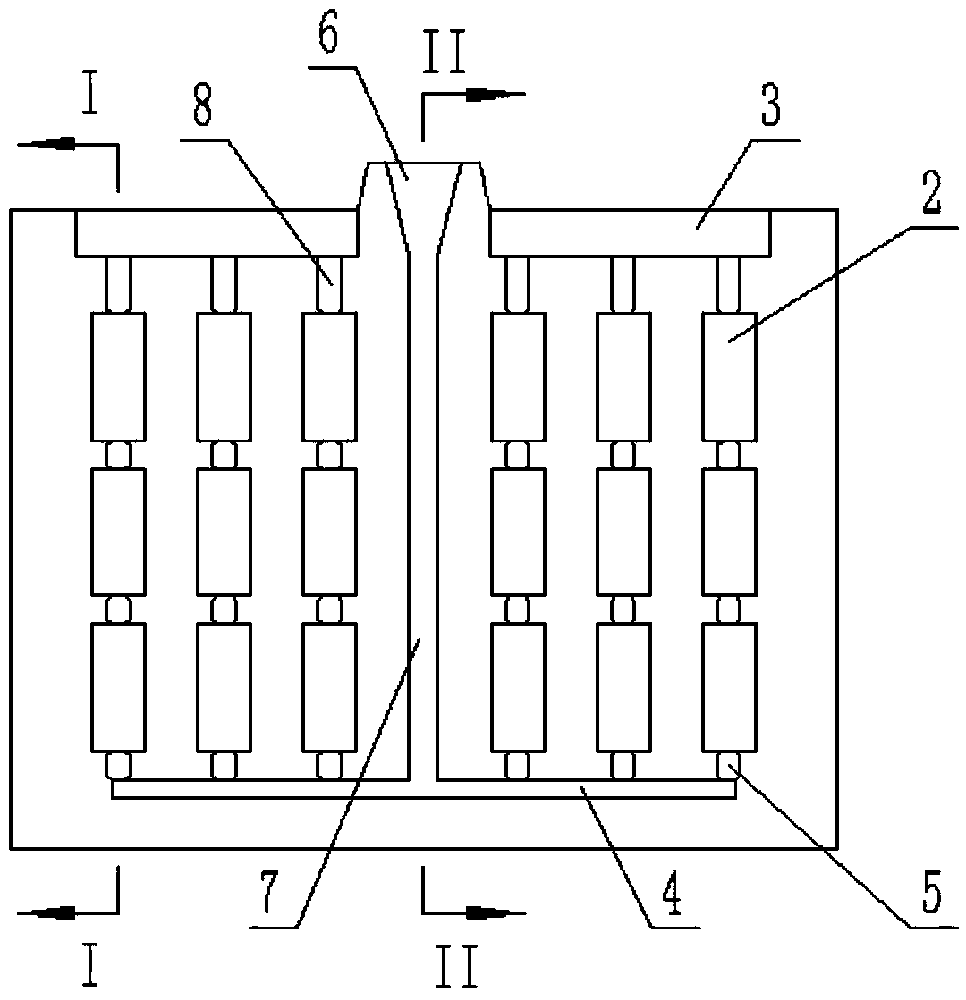
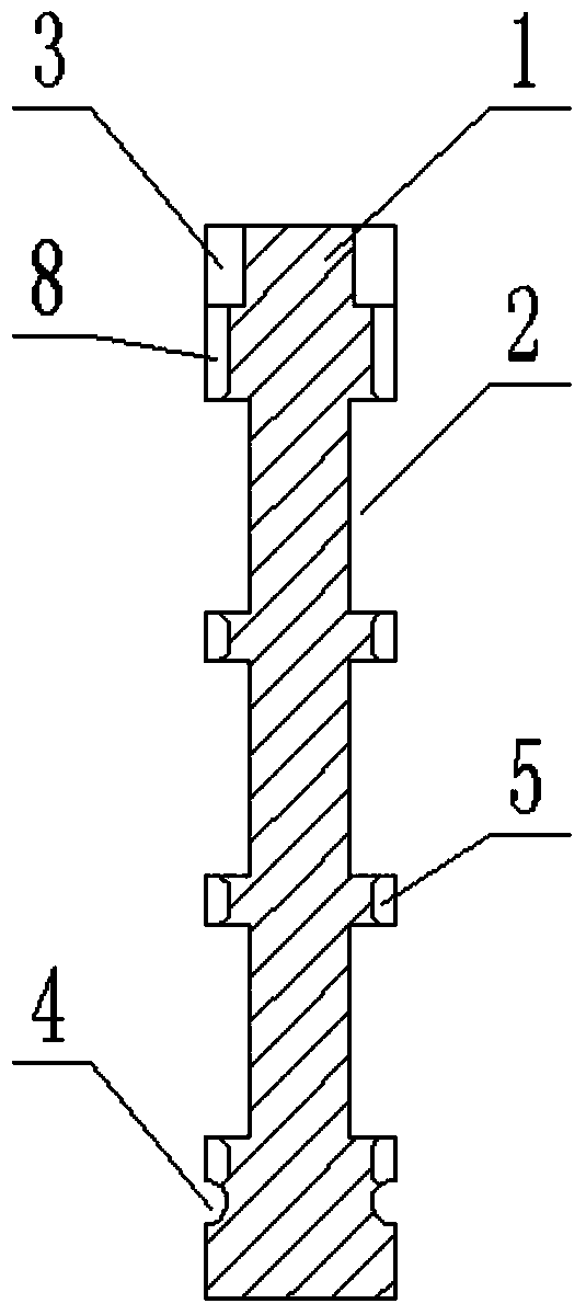
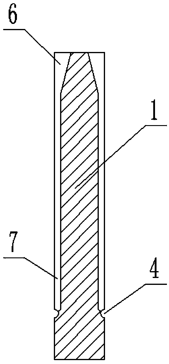
[0037] Embodiment 1: When a group of steel segments needs to be produced, it is the same as conventional casting at this time, that is, two modular monomers 1 are used for casting. Close the two modular monomers 1, at this time, the cavity 2, sprue 7, sprue 6, runner 4, ingate 5, overflow port 8 and overflow between the two modular monomers 1 The grooves 3 are closed one by one to form a complete casting channel, cavity and overflow channel; the molten iron is injected into the module body 1 through the two pouring ports 6, and the gas in the cavity moves upward and is discharged through the overflow port 8 , Bottom injection casting, molten iron flows upward from the runner 4 at the bottom, and fills the cavity 2 one by one. When the molten iron overflows from the overflow port 8 into the overflow tank 3, the cavity 2 is completely filled with molten iron. After the molten iron is cooled, disassemble the module unit 1 and take out the rough mold. Since the ends of the ingate ...

Embodiment 2

[0038] Embodiment 2: When it is necessary to produce multiple sets of steel sections, it is assumed that the number of module monomers 1 is S, and the number of steel section groups is n, that is, S=n+1, n=1, 2, 3... ..n. Taking two groups of steel segments as an example, such as Figure 4 As shown, the three modular monomers 1 are superimposed in sequence. At this time, the two sides of the middle module monomer 1 form a complete casting channel, cavity 2 and overflow channel respectively, that is, two sides of the middle module monomer 1 form two A complete casting system; inject molten iron into the three module bodies 1 through two complete casting ports 6, and the gas in the cavity 2 is discharged upwards through the overflow port 8, bottom injection casting, and the molten iron is poured horizontally from the bottom The channel 4 flows upwards and fills the complete cavity 2 one by one. When the molten iron overflows from the overflow port 8 into the overflow groove 3, ...


PUM


Abstract

The invention discloses a two-sided casting mold for steel section stack boxes. The two-sided casting mold comprises module monomers, wherein a plurality of cavities arranged in line are formed in the front and back side surfaces of the module monomers; ingates are formed in the bottoms of all the cavities; the cavities in the same line are connected through the ingates; straight gates are formed in the middles of the front and back side surfaces of the module monomers; cross gates perpendicular to the straight gates are formed in the bottom ends of the straight gates; and the top ends of the cross gates are communicated with the ingates in the bottoms of the cavities in the lowest line. The cavities, the inner cross gates and the straight gates are formed in the front and back sides of one module monomer, that is, the casting can be finished for two sides; n-1 complete cavities can be formed through stacking n module monomers in production for casting; and compared with traditional 2n module monomers, the usage amount is largely decreased, and the production cost is largely reduced.

Description

technical field [0001] The invention relates to the field of casting technology, in particular to a casting mold, in particular to a double-sided casting mold for stacked steel boxes. Background technique [0002] When some special material steels are processed into steel sections, casting molds are generally used for casting. The traditional casting method generally uses sand casting, that is, sand molds need to be sanded first when pouring; when sanding, the mold moves more times, and The utilization rate of molten iron is low, the finish of the finished product is low, the phenomenon of falling sand is serious, and the pouring time is long. In order to solve these problems, sandless casting molds are mostly used at present. However, the existing casting molds generally include two formworks on the left and right. The middle parts of the two formworks are oppositely opened with a cavity and a runner. The runner completes the casting process. [0003] The patent document...

Claims


Application Information

Patent Timeline
Patent Type & Authority Applications(China)
IPC IPC(8): B22C9/20B22C9/08
Inventor 汪福海
Owner ZUNYI JIUZHI GENERAL MACHINERY
Why Eureka
Try Eureka