
Springs for watch movements

A watch mechanism, mechanical technology, applied in the watch movement, correction mechanism or escapement mechanism, calendar mechanism, spring field of watch mechanism, can solve the problem of difficult to guarantee bending tolerance, spring industry and repeatable production, etc. question

Active Publication Date: 2018-05-29
ROLEX SA
View PDF8 Cites 0 Cited by
  • Summary
  • Abstract
  • Description
  • Claims
  • Application Information

AI Technical Summary

Problems solved by technology

However, dimensional tolerances are very tight and bending tolerances are very difficult to guarantee, which makes the industrial and repeatable production of such springs very problematic

Method used


Image

  • Springs for watch movements
  • Springs for watch movements
  • Springs for watch movements

Examples


Embodiment Construction

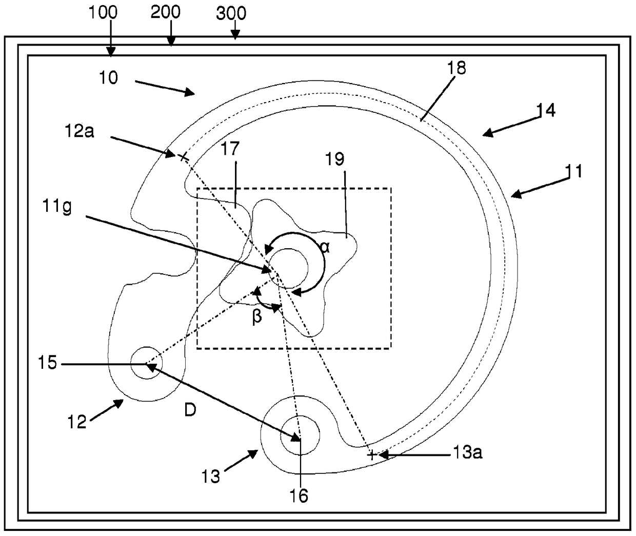
[0028] Refer below figure 1 A timer 300 according to the present invention is described. The timepiece is, for example, a watch, especially a wristwatch. The timepiece comprises a timepiece movement 200 , in particular a timepiece movement of the mechanical type. The timepiece movement comprises a mechanism 100 , in particular a mechanism comprising an element 19 and a spring 10 .

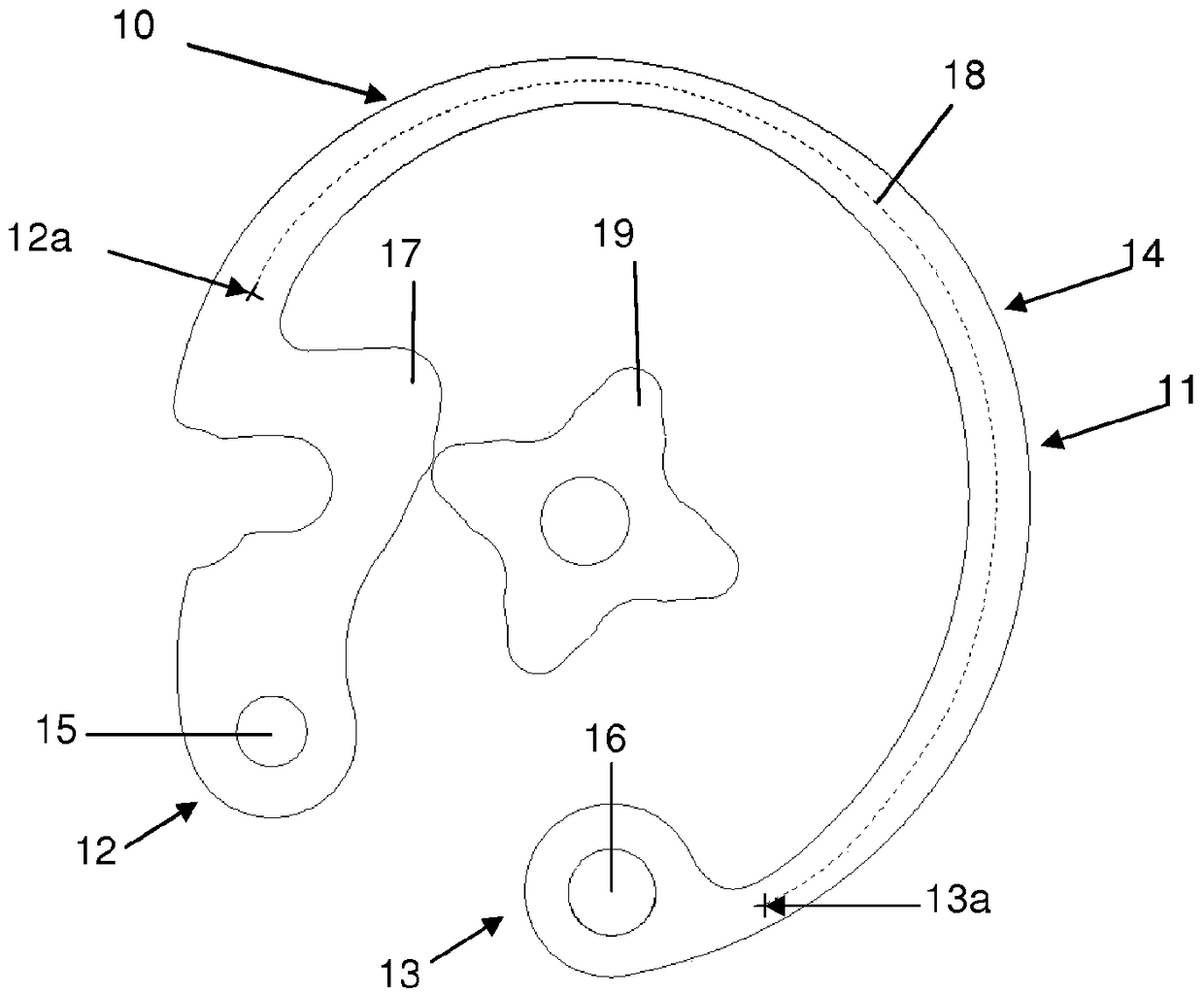
[0029] Refer below figure 1 with figure 2 A spring 10 for a timepiece or a first variant of a spring for a timepiece is described. Springs are used, for example, in timepiece mechanisms of the type that include devices for rapid correction of the time display. The spring 10 is arranged to interact, for example by contact with an element 19 of the timepiece, to generate escapement during correction, so as to allow adjustment of the time display by predetermined step angles. Springs are used to be mounted on the frame.

[0030] The spring 10 comprises a body 11 extending between a first end 1...


PUM


Abstract

A spring (30) for a timepiece mechanism comprising a body (31) extending between a first end (32) of the spring and a second end (33) of the spring, the spring being adapted to operate between the first and Mechanically connected to the case at a second end, between the first and second ends, the spring comprises at least one member (37) for acting by contact on an element of the timepiece mechanism.

Description

technical field [0001] The present invention relates to a spring for a timepiece mechanism, or a spring for a timepiece mechanism. The invention also relates to a timepiece mechanism, in particular a date mechanism, a corrector mechanism or an escapement mechanism, comprising such a spring. The invention also relates to a timepiece movement comprising such a spring or such a mechanism. Background technique [0002] A timepiece mechanism is usually provided with springs, levers and cams which interact to perform the various functions of the timepiece movement. The energy obtained from the drive and even supplied by the wearer of the watch is thus accumulated and released within a limited volume by means of the spring in a functionally guaranteed manner. Timepiece designs are therefore often limited by their physical size, which leads to spring geometries in which the mechanical stress relative to the force to be supplied is very high. In some cases a "wire" spring can be u...

Claims


Application Information

Patent Timeline
Patent Type & Authority Patents(China)
IPC IPC(8): G04B11/00G04B11/02G04B19/253
CPCG04B11/008G04B11/028G04B19/25373Y10T74/20636G04B19/25353G05G5/06
Inventor 克里斯蒂安·弗勒里布莱兹·弗拉舍布
Owner ROLEX SA
Learn More