
Method and receiver in wireless communication system

A wireless communication system and receiver technology, applied in transmission systems, multi-frequency code systems, digital transmission systems, etc., can solve problems such as poor performance and insufficient problem solving, and achieve the effect of improving performance

Active Publication Date: 2014-09-03
HONOR DEVICE CO LTD
View PDF4 Cites 2 Cited by
  • Summary
  • Abstract
  • Description
  • Claims
  • Application Information

AI Technical Summary

Problems solved by technology

[0031] However, estimators based on baseline frequency have two main problems: (i) approximating z k =Qs k ≈exp(i2πε FFO Δ)H k x k is only an approximation and introduces additional noise into the system
[0032] The second (ii) problem is that this approximation is limited to a maximum FFO1 / 2Δ
However, this algorithm performs poorly because it does not adequately address problem (i)

Method used


Image

  • Method and receiver in wireless communication system
  • Method and receiver in wireless communication system
  • Method and receiver in wireless communication system

Examples


Embodiment Construction

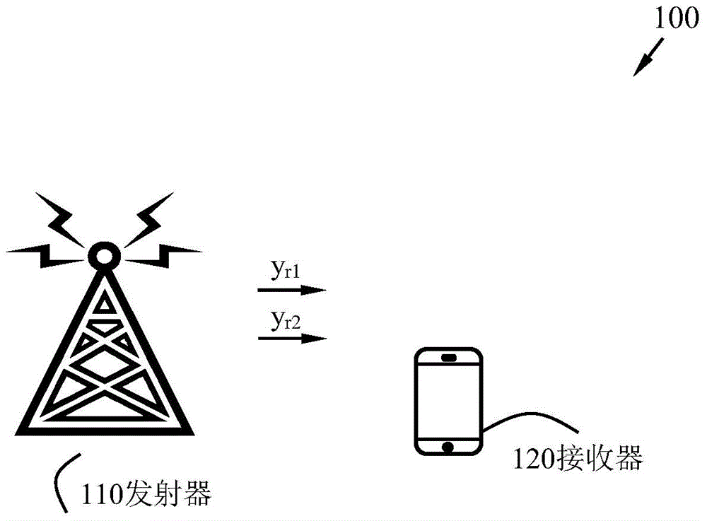
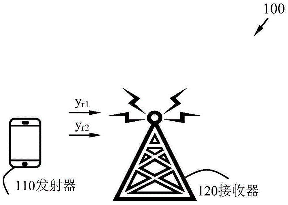
[0076] Embodiments described herein are defined as a receiver and a method in a receiver, which can be put into practice in the embodiments described below. These embodiments, however, may be exemplary and may be implemented in many different forms, and are not limited to the examples set forth herein; rather, illustrative examples of these embodiments are provided so that this disclosure will be thorough and complete .

[0077] Other objects and features will also become apparent from the following detailed description considered in conjunction with the accompanying drawings. It should be understood, however, that the drawings are for illustration only and not as a definition of the scope of the embodiments disclosed herein, for which scope reference should be made to the appended claims. In addition, the drawings are not necessarily drawn to scale and, therefore, unless otherwise indicated, are intended only to conceptually illustrate the structures and processes described ...


PUM


Abstract

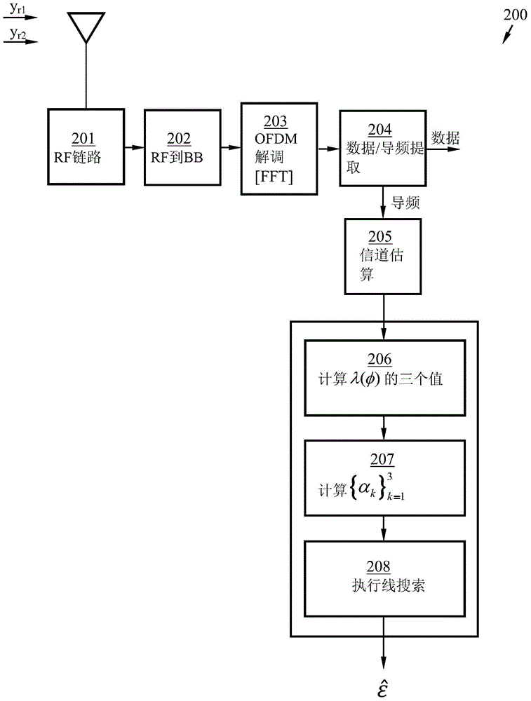
A receiver (120) and a method (400) for the receiver (120) are used for estimating normalized frequency deviation between a transmitter (110) in a wireless communication system (100) and the receiver (120) on the basis of orthogonal frequency division multiplexing (OFDM). The method (400) comprises receiving (401) a first pilot signal (yr1) and a second pilot signal (yr2) from the transmitter (110); calculating (402) a Carlo approximate value [lamda]K([fai]) based on the received (401) pilot signals (yr1, yr2) until any finite order K of a log-likelihood function [lamda]([fai]); and estimating the frequency deviation through calculating the maximum value of the calculated Carlo approximate value [lamda]K([fai]).

Description

technical field [0001] Embodiments described herein relate generally to a receiver and a method in a receiver, and in particular to a mechanism for estimating a frequency offset between a transmitter and a receiver in a wireless communication system. Background technique [0002] A User Equipment (UE), also known as a mobile station, wireless terminal and / or mobile terminal, is enabled for wireless communication in a wireless communication system (sometimes also referred to as a cellular wireless system or a wireless communication network). Communications may take place, eg, between UEs, between a UE and a wireline phone, and / or between a UE and a server, via a radio access network (RAN) and possibly one or more core networks. Wireless communications may include various communication services such as voice, messaging, packet data, video, broadcast, and so on. [0003] A UE may be further referred to as a mobile phone, a cellular phone, a tablet computer, or a wireless-capab...

Claims


Application Information

Patent Timeline
Patent Type & Authority Applications(China)
IPC IPC(8): H04L27/26
CPCH04L27/266H04L27/2684H04L27/2672H04L27/2675H04L27/2682H04L27/16
Inventor 鲁塞克·弗雷德里克巴苏基·恩达·帕里延多
Owner HONOR DEVICE CO LTD
Learn More