
A fixed pipe support

A pipeline support, fixed technology, applied in the direction of pipeline support, pipe/pipe joint/pipe fitting, mechanical equipment, etc., can solve the problems of lack of direct adjustment, installation, high manufacturing cost, and larger production, so as to reduce pipeline adjustment. work, strong application and promotion value, and the effect of highlighting substantive characteristics

Inactive Publication Date: 2017-05-31
JIGANG GRP
View PDF10 Cites 1 Cited by
  • Summary
  • Abstract
  • Description
  • Claims
  • Application Information

AI Technical Summary

Problems solved by technology

Due to the specificity of the installation environment, the medium in the pipeline and the production process of the pipeline system, some pipelines need to adjust the pipeline bracket after a certain period of time to meet the production requirements. The current pipeline system mainly uses fixed pipeline brackets, and the pipeline can only Sliding along the center line of the pipe, it does not have the function of direct adjustment in both horizontal and vertical directions. In order to meet the needs of production, it is usually used to make a new pipe bracket according to the new position, and then replace it, which will cause A certain amount of waste, especially for pipe supports in some special positions such as overhead, is more difficult to replace, the installation and manufacturing costs are higher, and greater expenses will be incurred. This is the deficiency of the existing technology

Method used


Image

  • A fixed pipe support

Examples


Embodiment Construction

[0015] In order to clearly illustrate the technical characteristics of this solution, the following describes this solution through a specific implementation and in conjunction with the accompanying drawings.

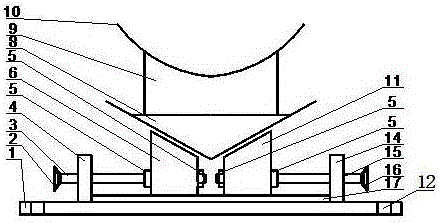
[0016] It can be seen from the drawings that a fixed pipe support includes a bottom plate 1 on which a slide groove 17 is provided. The slide groove 17 can be formed by welding two parallel steel strips on the bottom plate 1. The sliding groove 17 has a left slider 6 and a right slider 11, the bottom surface of the left slider 6 and the bottom surface of the right slider 11 are in contact with the bottom plate 1, and the side surfaces of the left slider 6 and the right slider 11 are respectively in contact with There is a certain gap between the side surfaces of the sliding groove 17 to ensure that the left slider 6 and the right slider 11 can move flexibly in the sliding groove 17 without being stuck. The left slider 6 and the right slider 11 are both connected with a hor...


PUM


Abstract

The invention provides a technical scheme of a stationary pipeline support. According to the scheme, the stationary pipeline support comprises a bottom plate, wherein a sliding groove is formed in the bottom plate, and a left sliding block and a right sliding block are arranged in the sliding groove and connected with a horizontal moving driving mechanism; a V-shaped bracket is erected on the upper surfaces of the left sliding block and the right sliding block, and the upper surfaces of the left sliding block and the right sliding block are wedge-shaped surfaces matched with the bottom surface of the V-shaped bracket; a tube bracket is fixed at the upper part of the V-shaped bracket. As the sliding groove is arranged and the left sliding block and the right sliding block are arranged in the sliding groove and matched with the V-shaped bracket for use, the relative distance between the left sliding block and the right sliding block and the positions of the left sliding block and the right sliding block in the sliding groove are adjusted so as to drive the position of the V-shaped bracket on the left sliding block and the right sliding block in horizontal and vertical directions, and finally the adjustment effect of a pipeline in the horizontal and vertical directions is realized.

Description

Technical field [0001] The invention relates to a bracket, especially a fixed pipeline bracket. Background technique [0002] In the pipeline design and installation process, a certain form of pipeline bracket is often set according to a certain interval. For some pipelines, due to the specificity of the installation environment, the medium in the pipeline and the production process of the pipeline system, the pipeline bracket needs to be adjusted after a certain period of time to meet the production requirements. The current pipeline system mainly uses fixed pipeline brackets. Sliding along the center line of the pipeline does not have the function of direct adjustment in both horizontal and vertical directions. In order to meet the needs of production, a new pipe bracket is usually made according to the new position and then replaced, which will cause Certain wastes, especially those in special positions such as overhead, are more difficult to replace, higher in installation a...

Claims


Application Information

Patent Timeline
Patent Type & Authority Patents(China)
IPC IPC(8): F16L3/16
CPCF16L3/16
Inventor 刘进贾瑞民廖敏徐瑞阳周家梅徐兆金张希营吴宝国王鲁济石玲翠
Owner JIGANG GRP
Learn More