
Flexible ironing groove structure of groove type ironing machine

An ironing machine and trough type technology, applied in the direction of ironing machine, washing device, textile and paper making, etc., can solve the problems of hindering popularization, unable to meet the ironing process, and the price of flexible trough type ironing machine remains high. Achieve the effect of reducing manufacturing difficulty and realizing machine flexibility

Active Publication Date: 2014-09-03
SHANGHAI WEISHI MACHINERY
View PDF10 Cites 9 Cited by
  • Summary
  • Abstract
  • Description
  • Claims
  • Application Information

AI Technical Summary

Problems solved by technology

[0005] However, the flexible trough ironing machine can only be adjusted flexibly in the traveling direction of the linen, that is, along the circumferential direction of the ironing trough. This adjustment is limited and is passively adjusted according to the shape and wear of the drum. This adjustability cannot change the distribution state of the pressure between the ironing tank and the cylinder (for example, the ironing pressure is required to be low before and high after the ironing pressure is uniformly increased), and it cannot meet the active demand changes of various ironing processes. In addition, the larger The cost of the entire flexible tank is expensive, and the area is large and the heating is uneven, resulting in the high price of the flexible tank ironing machine, which hinders its rapid popularization

Method used


Image

  • Flexible ironing groove structure of groove type ironing machine
  • Flexible ironing groove structure of groove type ironing machine
  • Flexible ironing groove structure of groove type ironing machine

Examples


Embodiment Construction

[0042] The present invention will be further described below in conjunction with accompanying drawing.

[0043] Figure 6~7 Among them, the ironing machine includes a horizontally arranged cylindrical drum 1 and an ironing tank 2 arranged below the drum 1, and both ends of the ironing tank 2 are open ends.

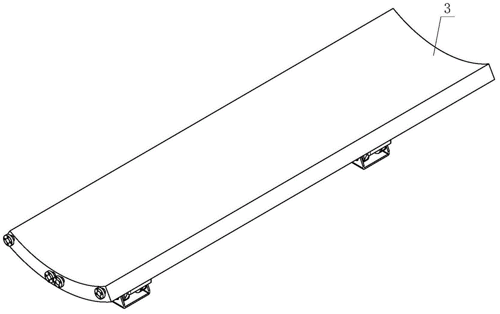
[0044] like Figure 4~5 As shown, the ironing tank 2 is divided into two segments along the axial direction, and each segment is divided into three tile-shaped heating blocks 3 along the circumferential direction to form a semicircular cavity. Arrange upwards into an orthogonal grid-like array.

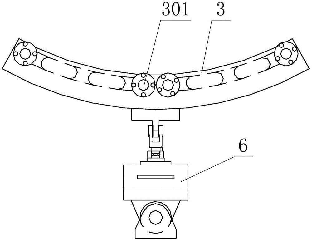
[0045] like Figure 1~2 As shown, the heating block 3 is provided with a heating device 301 and equipped with a temperature sensor.

[0046] like Figure 6~4 As shown, the concave surface of the ironing tank 2 is covered with a balanced heat conduction metal sheet 4, and the balanced heat conduction metal sheet 4 with a semicircular opening facing upwards is divided into two ...


PUM

PropertyMeasurementUnit
Thicknessaaaaaaaaaa
Thicknessaaaaaaaaaa

Abstract

The invention discloses a flexible ironing groove structure of a groove type ironing machine. The ironing machine comprises a cylindrical roller horizontally arranged, and a semicircular ironing groove formed below the roller, wherein the ironing groove is formed by splicing tile-shaped heating blocks which are divided into a plurality of sections in the axial direction, and each section of the tile-shaped heating blocks is divided into a plurality of blocks in the peripheral direction; an ironing groove support frame with an upward opening is arranged below the ironing groove; the length direction of a groove cavity of the ironing groove support frame is accordant with the axial direction of the ironing groove; pairs of ejection elements are respectively arranged between all the heating blocks and the ironing groove support frame close to the two ends of the heating blocks in the axial direction of the ironing groove; the axial lines of the ejection elements are accordant with the radial direction of the ironing groove; and the upper ends / lower ends of the ejection elements are rotationally connected with the heating blocks. The flexible ironing groove structure provides an ironing mode of active three-dimensional pressure servo adjustment and temperature control for ironing linen, and can satisfy different process control requirements of different linen types on the ironing quality.

Description

technical field [0001] The invention relates to a groove type ironing machine, in particular to a flexible ironing groove structure. Background technique [0002] The ironing machine is an important equipment for the ironing function of the washing machine, which belongs to the laundry room ironing equipment. Its main components are generally composed of single or multiple drums. The drums rotate at a low speed and constant speed. After the equipment reaches a certain temperature, when the wet clothes pass through the drums, a large amount of water can be removed, and the ironing effect can be achieved. The ironing machine is used for the flattening process of linen such as bed sheets, tablecloths, cloth and carpets. [0003] At present, common automatic ironing machines in laundry rooms include drum ironing machines and trough ironing machines. The drum ironing machines envelop the ironed linen on the surface of the heated and rotating drum in a certain arc. Iron dry in t...

Claims


Application Information

Patent Timeline
IPC IPC(8): D06F65/06
CPCD06F65/06D06F65/08
Inventor 王国顺吕立毅赵林
Owner SHANGHAI WEISHI MACHINERY
Learn More