Vertical cable pay-off device
A technology of pay-off device and cable, which is applied to the installation of cables, the arrangement of cables between relatively moving parts, electrical components, etc. Effort-saving, weight-saving, and stability-enhancing effects
- Summary
- Abstract
- Description
- Claims
- Application Information
AI Technical Summary
Problems solved by technology
Method used
Image
Examples
Embodiment 1
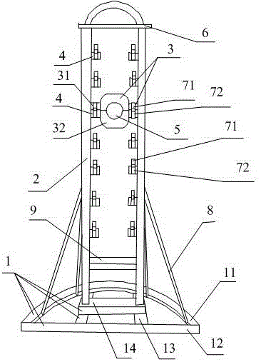
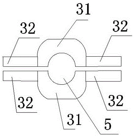
[0026] Such as figure 1 , 2 . As shown in 3, the vertical cable pay-off device includes a base 1, 2 uprights 2 vertically connected to the base 1, a limit plate 6 connected to the upper ends of the 2 uprights 2, and a support is provided between the 2 uprights 2 Mechanism 3, a plurality of fixed blocks 4 are evenly distributed from top to bottom on the two opposite end surfaces of the two columns 2, and the fixed blocks 4 are welded on the columns 2; the support mechanism 3 is composed of two support plates 31 and a support column 32, the support plate 31 is longitudinally arranged, and the center of the support plate 31 is provided with a semicircular groove 5, and one notch of the semicircular groove 5 of the two support plates 31 is set upward, and the other notch is set downward. The semicircular groove 5 constitutes a circular through groove, and the beam for fixing the coil can be fixed in the circular through groove; the two ends of the support plate 31 are respectivel...
Embodiment 2
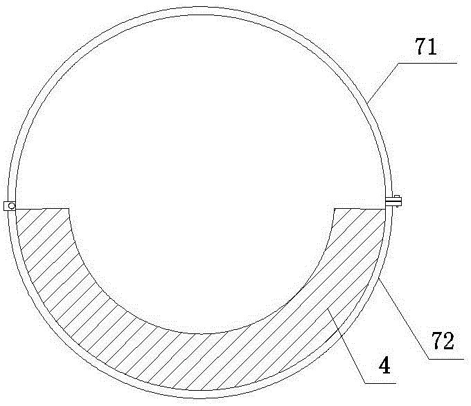
[0029] On the basis of Embodiment 1, the support column 32 of the vertical cable pay-off device in this embodiment is a semi-cylindrical structure; the fixed block 4 is a hollow semi-cylinder, image 3 It is a cross-sectional view of the fixed block. The inner diameter of the semi-cylindrical cylinder is equal to the radius of the support column 32, so the semi-cylindrical support columns 32 at both ends of the support plate 31 located below can just be placed in the fixed block 4 with the plane facing upwards and located at the top The semi-cylindrical support columns 32 at the two ends of the support plate 31 are placed on the plane downwards, and the support columns 32 of the two support plates 31 form a cylinder, the lower half of which is located in the semi-cylindrical fixed block 4, and the upper end passes through the upper The hoop 71 and the lower hoop 72 are fixed.
Embodiment 3
[0031] The difference between this embodiment and Embodiment 2 is that both the support column 32 and the fixed block 4 are rectangular parallelepiped structures, and the second groove on the fixed block 4 is also rectangular parallelepiped. The support columns 32 are the same, and the height is twice as high as the support columns 32, so that the two support columns 32 are conveniently placed in the second groove, and then fixed by two clamps.
PUM
 Abstract
Description
Claims
Application Information
 - R&D
- Intellectual Property
- Life Sciences
- Materials
- Tech Scout
- Unparalleled Data Quality
- Higher Quality Content
- 60% Fewer Hallucinations
Browse by: Latest US Patents, China's latest patents, Technical Efficacy Thesaurus, Application Domain, Technology Topic, Popular Technical Reports.
© 2025 PatSnap. All rights reserved.Legal|Privacy policy|Modern Slavery Act Transparency Statement|Sitemap|About US| Contact US: help@patsnap.com


