
Liquid crystal display device

A liquid crystal display and liquid crystal display panel technology, applied in lighting and heating equipment, lighting devices, optics, etc., can solve the problems that the thickness of the frame of the display device is difficult to reduce, cannot be used as a mixing distance, and fireflies appear, so as to reduce the phenomenon of fireflies, Reduce the effect of light and dark interlacing and increase the distance of light mixing

Inactive Publication Date: 2014-08-27
TOP VICTORY INVESTMENTS
View PDF5 Cites 3 Cited by
  • Summary
  • Abstract
  • Description
  • Claims
  • Application Information

AI Technical Summary

Problems solved by technology

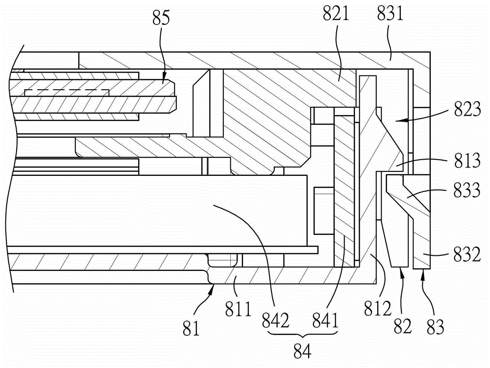
[0005] However, in the aforementioned liquid crystal display device, the combination of the iron frame 83, the plastic frame 82 and the back shell 81, the distance from the first side wall 812 to the third side wall 832 will cause the overall liquid crystal The thickness of the frame of the display device is difficult to reduce, and it cannot be used as a light mixing distance
Therefore, if the structure remains unchanged, once the number of LEDs is reduced in order to reduce costs, firefly phenomena will appear at the edge of the effective light-emitting area

Method used


Image

  • Liquid crystal display device
  • Liquid crystal display device
  • Liquid crystal display device

Examples


Embodiment Construction

[0027] Before the present invention is described in detail, it should be noted that in the following description, the directional terms mentioned in the present invention, such as "upper", "lower", "top", "bottom", etc., are only for reference to the attached drawings. style direction. Accordingly, the directional terms are used to illustrate, not to limit, the invention.

[0028] The present invention will be described in detail below with reference to the accompanying drawings and a preferred embodiment.

[0029] refer to Figure 5 and Image 6 A preferred embodiment of a liquid crystal display device of the present invention includes a bottom case 1 , an inner frame 2 , a front frame 3 , a liquid crystal display panel 7 and a side-lit backlight module 6 .

[0030] refer to Image 6 and Figure 7 , the bottom shell 1 is made of iron, and has a square bottom wall 11, a side wall 12 extending upward from one of the outer edges of the bottom wall 11, and a side wall 12 ext...


PUM


Abstract

Disclosed is a liquid crystal display device. The liquid crystal display device comprises a bottom case, an inner frame, a front frame, a liquid crystal display panel and a side light type backlight module. The bottom case comprises a bottom ball, a side wall extending from one outer edge of the bottom wall, a base wall extending inwards from the top end of the side wall, and a plurality of upper protrusion units extending upwards from the top surface of the base wall; the inner frame is integrated onto the bottom case to define a first accommodating space and provided with a plurality of through holes for the protrusion units to penetrate and a plurality of upwards-opened lower recess units; the front frame is arranged on the inner frame to define a second accommodating space and provided with a plurality of downwards-protruded lower protrusion units combined with the lower recess units; the liquid crystal display penal is arranged inside the second accommodating space; the side light type backlight module is arranged inside the first accommodating space and comprises a light strip, which is arranged on the side wall and faces inwards.

Description

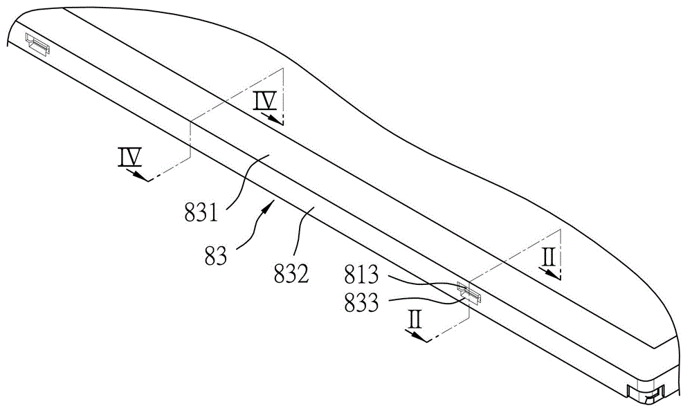
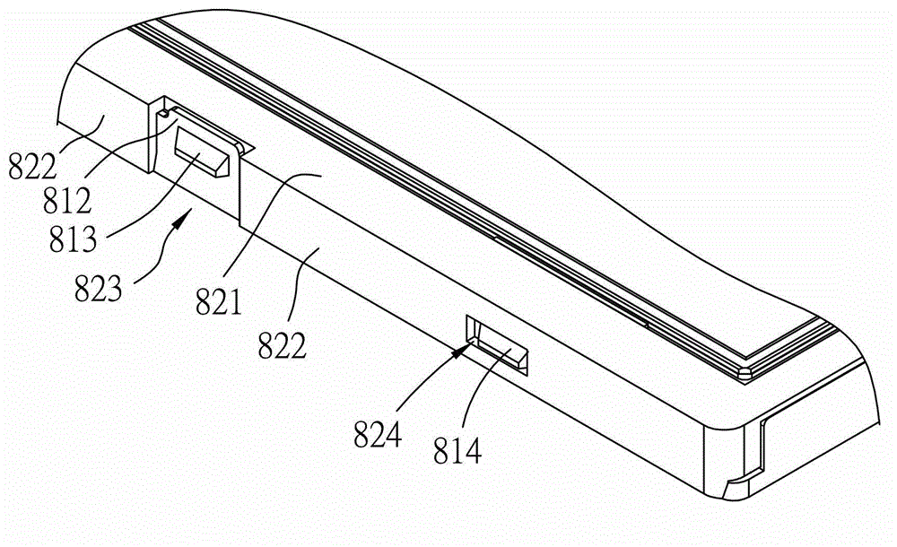
technical field [0001] The invention relates to a liquid crystal display device, in particular to a liquid crystal display device using a side-light backlight module. Background technique [0002] With the increasing development of the electronic industry, electronic products such as mobile phones and notebook computers are also rapidly introducing new ones. When the user is using these electronic products, the liquid crystal display device is an indispensable interface, and the user must operate the above-mentioned electronic products conveniently through the display of the liquid crystal display device. [0003] refer to figure 1 and figure 2 , a conventional liquid crystal display device includes a back cover 81 , a plastic frame 82 , an iron frame 83 , a backlight module 84 , and a liquid crystal display panel 85 . The back shell 81 has a square back plate 811, a first side wall 812 extending from an outer edge of the back plate 811, a plurality of first locking bloc...

Claims


Application Information

Patent Timeline
IPC IPC(8): G02F1/13357G02F1/13F21V21/00F21Y101/02F21Y103/10F21Y115/10
Inventor 陈明湶曾世均林心薇
Owner TOP VICTORY INVESTMENTS
Learn More