
Pole and tower power transmission line fault indicator

A fault indicator and transmission line technology, applied in the fault location and other directions, can solve the problems of the numerical error of the fault ranging system, the unreasonable setting value of the ranging system, the inconvenience of fault location and processing, etc., so as to achieve low standby power consumption and shorten the Fault location time, the effect of convenient, rapid and accurate judgment

Inactive Publication Date: 2014-08-27
STATE GRID CORP OF CHINA +2
View PDF8 Cites 10 Cited by
  • Summary
  • Abstract
  • Description
  • Claims
  • Application Information

AI Technical Summary

Problems solved by technology

[0003] At present, the fault finding of transmission lines is still based on the fault range calculated by the fault distance measurement system. Large error, increasing the scope of fault finding
In addition, the fault location system can only determine the fault range, and the fault site lacks a device that can be intuitively indicated to indicate the location of the fault. The inspection personnel need to judge by experience when fault finding, and it is difficult to find faults for some transient faults with no obvious traces. It often requires experienced inspectors to make multiple cross inspections to find the fault location, which brings great inconvenience to quick fault location and handling

Method used


Image

  • Pole and tower power transmission line fault indicator
  • Pole and tower power transmission line fault indicator
  • Pole and tower power transmission line fault indicator

Examples


Embodiment 1

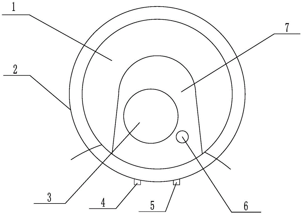
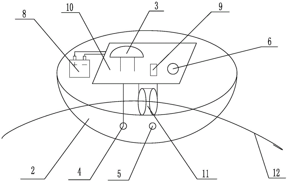
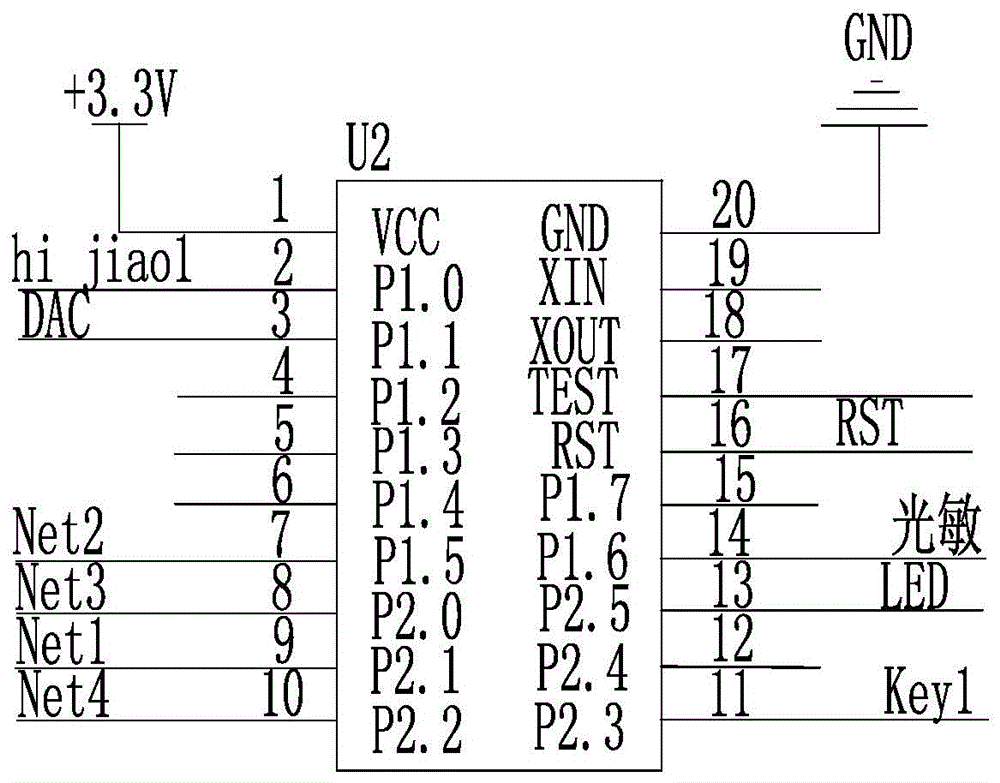
[0046] Such as figure 1 , figure 2 , Figure 10 As shown, a current transformer 11 and a control circuit board 10 are installed on the base of the tower transmission line fault indicator of the present invention, and the MCU processor and the power conversion circuit module connected with the MCU processor are arranged on the control circuit board 10, Filtering rectification amplifier circuit module, flop indicator motor positive and negative drive circuit module, photoresistor circuit connection module, LED warning light circuit connection module and reset circuit module, current sensor 11 is connected to MCU processor, MCU through filter rectification amplifier circuit module The processor drives the forward and reverse circuit of the motor to make the flop indicator act. When the light is relatively dark, in order to prevent the flop indicator from being unclear, the MCU processor controls the LED warning light to turn on, and the light signal is detected by the photoresi...

Embodiment 2

[0055] Such as Figure 11 As shown, on the basis of Embodiment 1, the wireless radio frequency communication module is connected to the MCU processor. The wireless radio frequency communication module uses the GSM module as the output actuator, and the position information of the transmitting tower of the control signal through the built-in program of the MCU processor, such as line name, voltage level and tower number, etc. The position information can be set in advance in the built-in program of the MCU processor. program. When the transmission line is in normal operation and no current flows, the device is in a dormant state with low power consumption. When a ground fault occurs and current flows through the tower, the device performs the action of Embodiment 1, that is, the flop indicator operates, and the LED warning light is based on the photosensitive The resistance indicates the detection of the light, and the MCU processor also controls the radio frequency communicat...


PUM


Abstract

The invention relates to a high-voltage power transmission line grounding fault indicating and positioning device, in particular to a pole and tower power transmission line fault indicator and belongs to the technical field of electric power tools. The pole and tower power transmission line fault indicator comprises a base, a current transformer and a control circuit board connected with a power source are arranged on the base, an MCU processor is welded to the control circuit board, the secondary current output end of the current transformer is connected with the signal input end of the MCU processor through a rectifying and filtering circuit and an amplifying circuit which are arranged on the control circuit board, the signal input end of the MCU processor is further connected with a photoresistor, the control output end of the MCU processor is respectively connected with a turnover indicator and an LED caution light, a semicircular shell is arranged above the base, a display window is arranged on the semicircular shell, and the display window corresponds to the turnover indicator, the LED caution light and the photoresistor which are arranged on the base. The pole and tower power transmission line fault indicator is simple in structure, the fault of a power transmission line can be fast and accurately positioned, the fault finding difficulty is reduced, the workload and the labor intensity of inspection personnel are reduced, and stable and reliable power supply is guaranteed.

Description

technical field [0001] The invention relates to a high-voltage transmission line grounding fault indication and positioning device, in particular to a tower transmission line fault indicator, which belongs to the technical field of electric tools. Background technique [0002] The safe and reliable operation of high-voltage transmission lines is related to the safety and stability of the entire power system. Therefore, more and more attention has been paid to the safe operation of transmission lines. Both in terms of management and technology, it is required to quickly and accurately locate faults in transmission lines. Eliminate to ensure stable and reliable power supply. [0003] At present, the fault finding of transmission lines is still based on the fault range calculated by the fault distance measurement system. Larger errors increase the scope of fault finding. In addition, the fault location system can only determine the fault range, and the fault site lacks a devi...

Claims


Application Information

Patent Timeline
Patent Type & Authority Applications(China)
IPC IPC(8): G01R31/08
Inventor 咸日常蒋涛孔祥清陈文栋朱锋杨学杰李宋林王世涛李思毛孙业龙
Owner STATE GRID CORP OF CHINA
Learn More