Steering wheel direction moving mechanism

A steering wheel and rotating disc technology, applied in steering mechanisms, steering mechanisms, steering mechanisms with deflectable wheels, etc., can solve problems such as chains that are easily rusted, easily broken or deformed, and the large rotational resistance of the steering wheel affects safe operation. The effect of low steering resistance and easy steering

Active Publication Date: 2014-08-27
FOSHAN GEMEI CLEANING EQUIP
View PDF3 Cites 6 Cited by
  • Summary
  • Abstract
  • Description
  • Claims
  • Application Information

AI Technical Summary

Problems solved by technology

[0004] The direction drive structure of the existing sweeping vehicle is to directly drive the large sprocket mounted on the upper end of the front wheel to drive the steering of the front tire by connecting the chain with the small sprocket on the small shaft. Therefore, the following disadvantages are arranged: 1. The steering wheel rotates Too much resistance affects safe operation; 2. The chain is easy to rust or break; 3. The steering angle of the front wheel is easily broken or deformed by the collision of the positioning pin; 4. The steering wheel is limited in the installation position of the vehicle

Method used


Image

  • Steering wheel direction moving mechanism
  • Steering wheel direction moving mechanism
  • Steering wheel direction moving mechanism

Examples


Embodiment

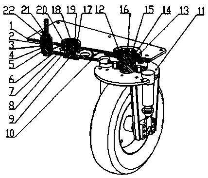
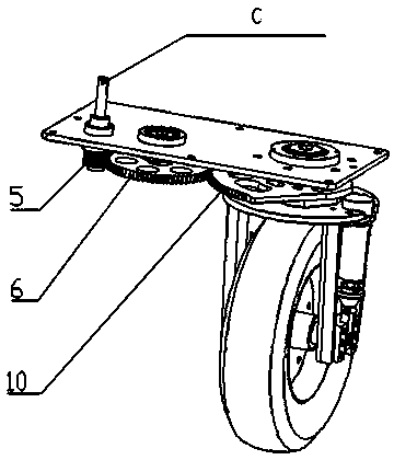
[0028] The invention discloses a steering wheel steering mechanism, which is driven by three gears engaged with each other; wherein the rotating disk gear is provided with sector-shaped external teeth;

[0029] The steering wheel steering mechanism relies on three gears to engage and drive to realize the direction offset steering, and the existing generally relies on the chain to drive the sprocket to realize the steering, that is, relying on the chain to drive the two sprockets to synchronously drive the same direction to achieve steering, However, the steering wheel steering mechanism of the present embodiment realizes the steering by means of three gears meshing and driving at first synchronously and in different directions, and then transitioning to synchronous and same-direction transmission. Since there is a transition gear in the middle, the offset distance transmission is realized from the input (removing the pinion) to the output (rotating disk), and the purpose of off...


PUM


Abstract

The invention discloses a steering wheel direction moving mechanism. Synchronization opposite-direction transmission is carried out by meshing of three gears, then synchronization identical-direction transmission is carried out in a transition mode, and steering is achieved. A transition gear is arranged in the middle, so that offset distance transmission from input (an opposite-moving small gear) to output (a rotating disc) is achieved, and the purpose of offset steering is achieved. The opposite-moving small gear, the transition gear and the rotating disc in the steering wheel direction moving mechanism are arranged on a direction component fixing plate. The opposite-moving small gear, the transition gear and a rotating disc gear are arranged on the same plane in a meshing-transmission mode for transmission, and three points at the mounting center are on the same straight line. The rotating disc is provided with a sector tooth face, and the two ends of the sector tooth face are provided with rotating angle limiting clamping positions for limiting the rotating angle quantity of the rotating disc respectively. The rotating disc is arranged on a main shaft of a front wheel fork frame component in a sleeved mode. Offset steering of a direction is achieved through meshing transmission of the three gears, and meshing transmission of the three gears is carried out from synchronization opposite-direction transmission to synchronization identical-direction transmission in a transition mode.

Description

technical field [0001] The invention relates to the field of single-wheel steering systems of electric three-wheel sweepers, and more particularly, to a steering wheel moving mechanism. Background technique [0002] In the field of single-wheel steering system of electric three-wheel sweeper, the steering wheel offset device is operated on one side of the vehicle, so that the driving position is driven by the vehicle body, which is convenient for better observation of roadside obstacles when driving the sweeper. and sweeping effect status. [0003] At present, the existing electric three-wheel sweepers are all driven by the rear two wheels, and the front single wheel is used for direction steering. They are all driving operations with the steering wheel in the middle. The principle is that the steering wheel and the steering wheel are installed in the middle of the vehicle. It is connected to a pipe rotating shaft by holding the steering wheel, and then the pipe rotating sh...

Claims


Application Information

Patent Timeline
Patent Type & Authority Applications(China)
IPC IPC(8): B62K21/00B62D3/12B62D9/00
Inventor 苏献
Owner FOSHAN GEMEI CLEANING EQUIP
Why Eureka
Try Eureka