mitral annuloplasty ring
A technique for forming annulus and mitral valve, which is applied in the field of medical devices, can solve the problems of complex motion, does not conform to the physiological motion law of the mitral valve annulus, cannot realize coordinated motion, etc., and achieves the effect of simple structure
- Summary
- Abstract
- Description
- Claims
- Application Information
AI Technical Summary
Problems solved by technology
Method used
Image
Examples
Embodiment 1
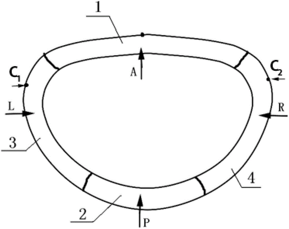
[0043] figure 2 It is a structural schematic diagram of the mitral annuloplasty ring described in Example 1.
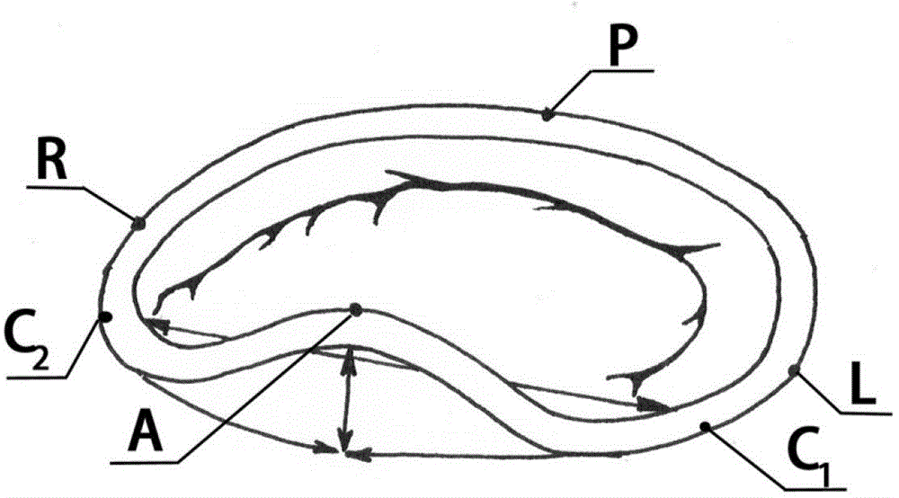
[0044] This embodiment discloses a mitral annuloplasty ring that can reshape the diseased mitral valve ring into a normal physiological shape and contour, such as figure 2 As shown, the mitral annuloplasty ring includes a ring body, which is a closed ring body integrally formed by a front ring segment 1, a rear ring segment 2, a left ring segment 3 and a right ring segment 4, specifically, the ring body An annular ring is formed for a closed saddle with a three-dimensional structure, and the annular body is provided with two soft segments and two hard segments at intervals along the periphery. That is, the mitral annuloplasty ring in this embodiment adopts a four-stage design: among the two arcuate protrusions of the saddle-shaped ring, the higher arcuate protrusion is the front ring segment 1, and the lower arcuate protrusion is the rear ring segment 2. The two c...
Embodiment 2
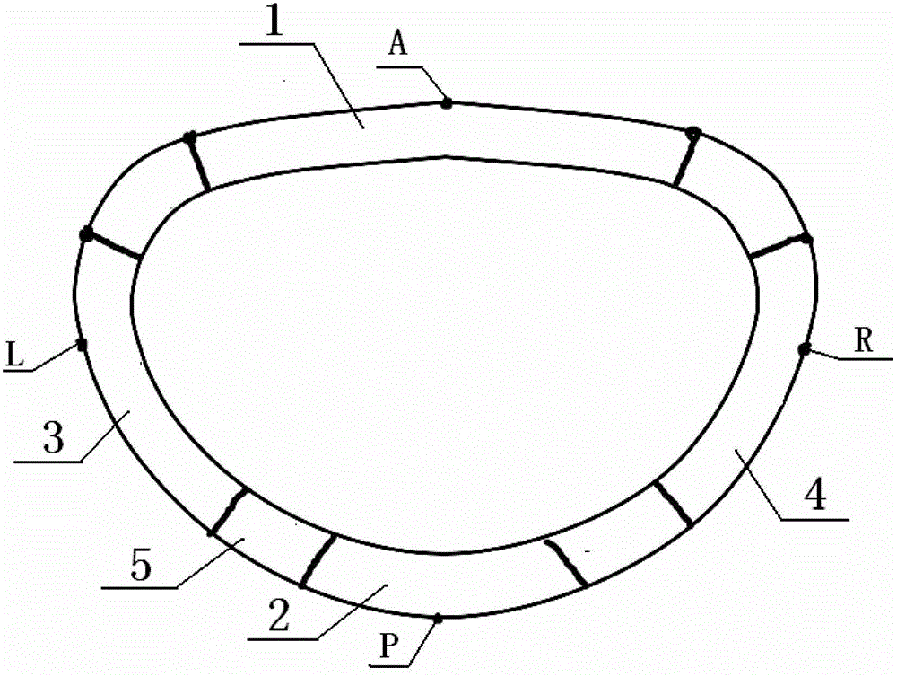
[0049] image 3 It is a structural schematic diagram of the mitral annuloplasty ring described in Example 2.
[0050] This embodiment discloses a mitral annuloplasty ring that can reshape the diseased mitral valve ring into a normal physiological shape and contour, such as image 3 As shown, the mitral annuloplasty ring includes a ring body, which is a closed ring body integrally formed by a front ring segment 1, a rear ring segment 2, a left ring segment 3 and a right ring segment 4, specifically, the ring body A shaped ring is formed for a closed saddle with a three-dimensional structure, and the ring body is provided with four soft segments and four hard segments at intervals along the peripheral direction. Among the two bow-shaped protrusions of the saddle-shaped ring, the higher bow-shaped protrusion is the front ring segment 1, and the lower arc-shaped protrusion is the rear ring segment 2; the two concave segments of the saddle-shaped ring are respectively the left rin...
Embodiment 3
[0057] Figure 4 It is the mitral annuloplasty ring structure described in Embodiment 3.
[0058] The mitral annuloplasty ring disclosed in this embodiment is basically the same as in embodiment 2. The difference from embodiment 2 is that the anterior ring section 1 and the rear ring section 2 of the mitral annuloplasty ring disclosed in this embodiment are provided with adjustable The adjustment line 6 of the distance between the front ring segment 1 and the rear ring segment 2, such as Figure 4 As shown, the adjustment line 6 in this embodiment is a Gore-Tex line, two threading holes are symmetrically arranged on the front ring section 1, and the distance between the two threading holes on the front ring section 1 and the highest point of the front ring section 1 is Both are 2mm, the highest point of the rear ring section 2 is provided with a threading hole, the adjustment line 6 is movable through the two threading holes of the front ring 1, and the two ends of the adjust...
PUM
 Abstract
Description
Claims
Application Information
 - Generate Ideas
- Intellectual Property
- Life Sciences
- Materials
- Tech Scout
- Unparalleled Data Quality
- Higher Quality Content
- 60% Fewer Hallucinations
Browse by: Latest US Patents, China's latest patents, Technical Efficacy Thesaurus, Application Domain, Technology Topic, Popular Technical Reports.
© 2025 PatSnap. All rights reserved.Legal|Privacy policy|Modern Slavery Act Transparency Statement|Sitemap|About US| Contact US: help@patsnap.com


