
A kind of infrared waveform detection method

A waveform detection and infrared technology, applied in transmission monitoring, signal transmission systems, instruments, etc., can solve the problems of slow speed and easy misreading of manual reading data, and achieve high sampling rate, large amount of data, accurate and intuitive display Effect

Active Publication Date: 2017-06-16
FUJIAN LILLIPUT OPTOELECTRONICS TECH
View PDF10 Cites 0 Cited by
  • Summary
  • Abstract
  • Description
  • Claims
  • Application Information

AI Technical Summary

Problems solved by technology

[0009] In view of this, the present invention provides a deep storage oscilloscope with an infrared code analysis function and an infrared waveform detection method that has a large amount of data, a high sampling rate, and can quickly and accurately display the details of infrared signals. The oscilloscope has a clear resolution and can accurately Analyze the coding information of infrared remote control, overcome the disadvantages of slow manual search one by one and easy misreading of manual reading data when using traditional methods to measure infrared remote control signals, and greatly improve the development efficiency of R&D personnel

Method used


Image

  • A kind of infrared waveform detection method
  • A kind of infrared waveform detection method
  • A kind of infrared waveform detection method

Examples


Embodiment 1

[0036] Embodiment 1. When the research and development personnel need to verify and detect the infrared signal sent by the infrared remote controller;

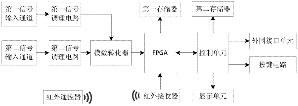
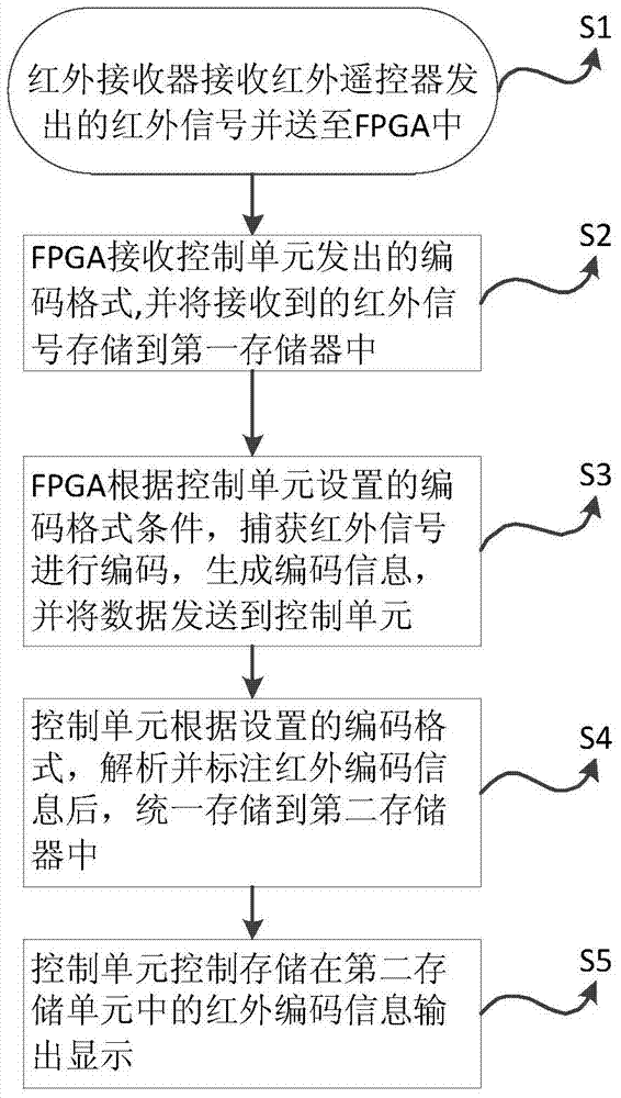
[0037] The infrared receiver receives the infrared signal sent by the infrared remote controller and transmits it to the FPGA, and the controller controls the infrared signal to be displayed on the display unit. In this way, the infrared signal can be automatically extracted and displayed intuitively.

Embodiment 2

[0038] Embodiment 2, when the research and development personnel need to detect or adjust the infrared remote control circuit according to the displayed infrared waveform;

[0039] Use the signal input channel of the oscilloscope to receive the external analog signal and send it to the analog-to-digital converter after being processed by the signal conditioning circuit, and then send the analog signal received by the signal input channel to the display unit for display through the FPGA and the control unit. It meets the needs of R&D personnel for circuit waveform detection of the infrared remote control device itself.

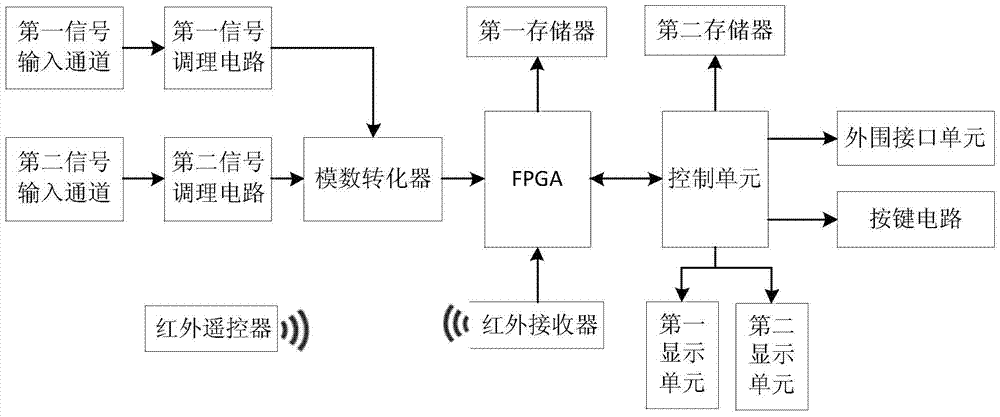
[0040] Such as figure 2 As shown, in embodiment three, when the research and development personnel need to detect or adjust the infrared remote control circuit according to the displayed infrared waveform; two display units can be used, the first display unit is used to display the waveform checked in the infrared remote control circuit, and the second The di...


PUM


Abstract

The invention discloses an infrared waveform detection method, which includes a signal input channel, a signal conditioning circuit, and an analog-to-digital converter, and the oscilloscope also includes an FPGA, a control unit, first and second memories, an infrared receiver, and a display unit; Described FPGA is respectively connected with the first memory, analog-to-digital converter, control unit and infrared receiver; Described control unit is also connected with the second memory and display unit; In this oscilloscope, described infrared receiver receives infrared signal, And transmit it to the FPGA, and the controller controls the infrared signal to be displayed on the display unit. The invention can not only meet the requirement of traditional waveform detection, but also can automatically extract and display the infrared signal.

Description

technical field [0001] The invention relates to the field of oscilloscopes, in particular to an infrared waveform detection method. Background technique [0002] The oscilloscope is an electronic measuring instrument with a wide range of uses. It is widely used in scientific research, teaching, engineering and other fields to detect the waveforms of various signals. The oscilloscope receives the detected analog signals through the information input channel, and A / After D conversion, the detected signal waveform will be displayed on the display through a series of adjustments. [0003] Infrared communication technology does not require physical connection, is easy to use and has low implementation cost, so it is widely used in small mobile devices to exchange data and control electrical equipment, such as between laptops, PDAs, mobile phones or between computers. Data exchange (personal network), remote control of TV, air conditioner, etc. [0004] Traditionally, semicondu...

Claims


Application Information

Patent Timeline
Patent Type & Authority Patents(China)
IPC IPC(8): G08C23/04H04B17/00
Inventor 葛水焕陈焕洵
Owner FUJIAN LILLIPUT OPTOELECTRONICS TECH
Learn More