
Device for laying out printed products fed in a single product flow into two separate stacks

A technology for printing products and product flow, applied in metal processing equipment, conveyors, transportation and packaging, etc., can solve problems such as expensive, inability to obtain output of printed products of different specifications, and components that are easily disturbed.

Inactive Publication Date: 2014-08-20
MULLER MARTINI HLDG
View PDF8 Cites 23 Cited by
  • Summary
  • Abstract
  • Description
  • Claims
  • Application Information

AI Technical Summary

Problems solved by technology

No suggestion can be drawn from the above-mentioned documents to output printed products with different formats into several mutually independent stacks without production interruption, and the equipment disclosed in the above-mentioned documents also does not allow Change specification settings
[0003] Furthermore, the above-mentioned cross stackers and book block stackers are relatively technically complex and, since the components that move with the machine cycle are prone to disturbances and are expensive, these machines are mainly used in conjunction with high-production printing machines, which however are Small batch orders are usually too expensive
[0004] Another problem with the above-mentioned cross stackers and book block stackers is that they cannot be used simultaneously as output devices for multiple perfect binders, or for processing products from one or more digital printing machines, because due to lack of Mixed runs with different print products or print products with different formats not possible due to changeover during standstill for different formats

Method used


Image

  • Device for laying out printed products fed in a single product flow into two separate stacks
  • Device for laying out printed products fed in a single product flow into two separate stacks
  • Device for laying out printed products fed in a single product flow into two separate stacks

Examples


Embodiment Construction

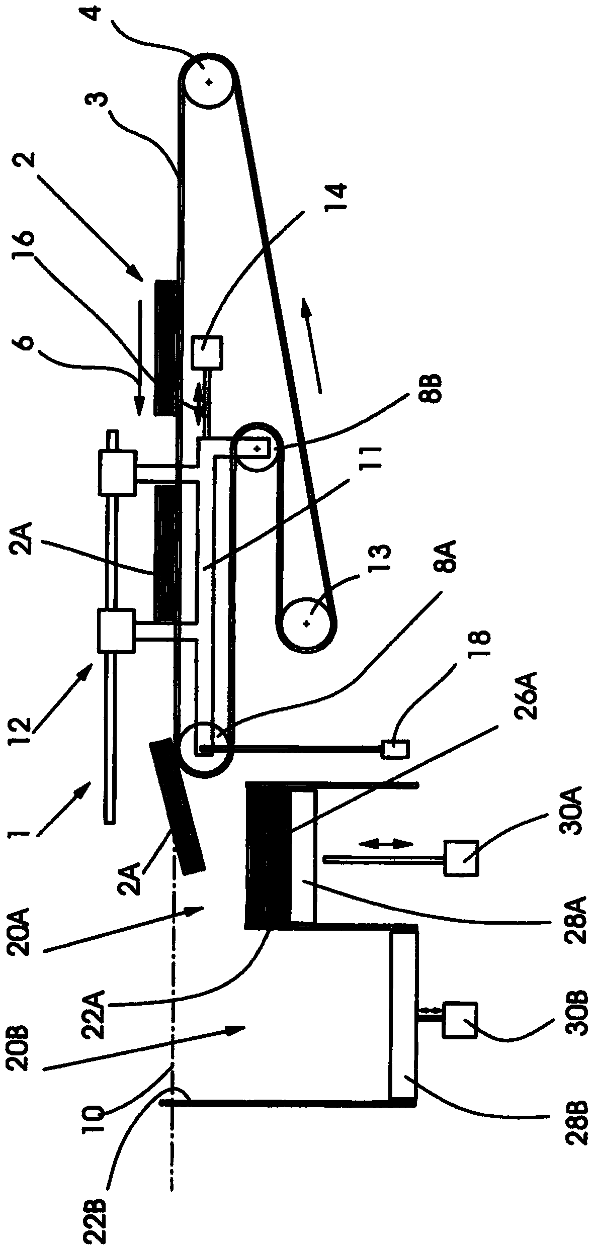
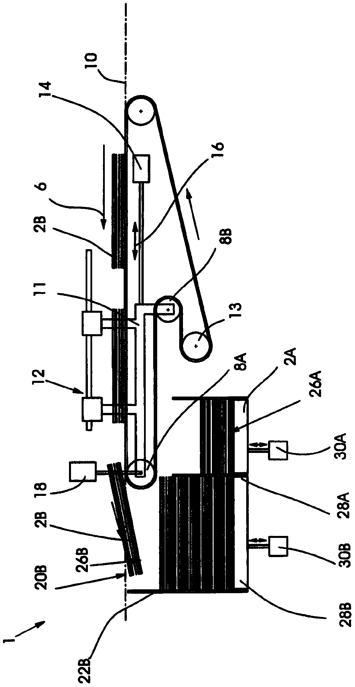
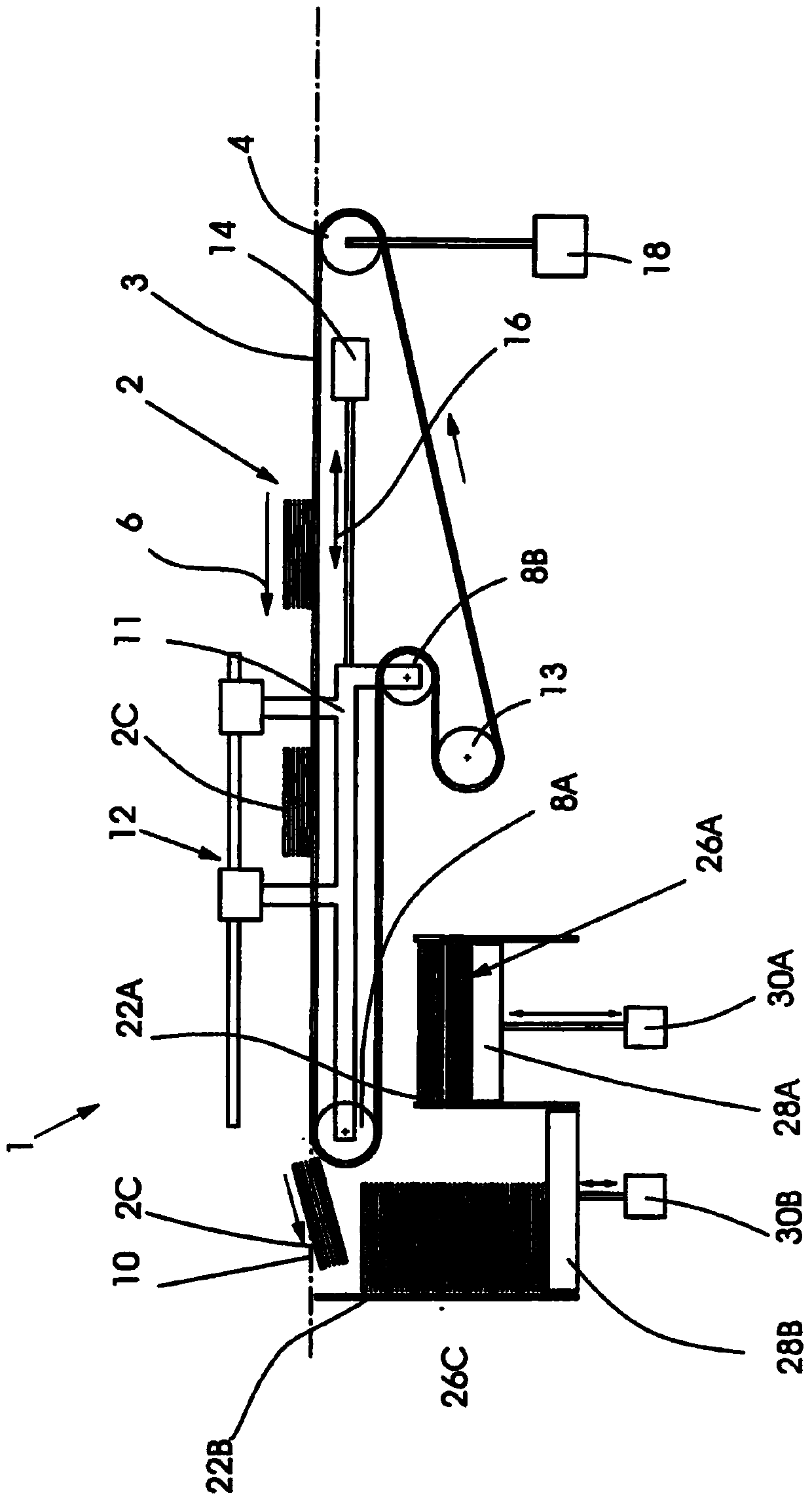
[0030] Such as Figures 1 to 5 As shown, the device 1 according to the invention for outputting printed products 2A, 2B, 2C provided in a product flow 2 comprises a revolving conveyor belt 3, after the printed products are conveyed by a not shown, upstream printing press ( The printed products 2A, 2B, 2C are placed on said conveyor belt after production, eg by a digital printing machine or a perfect binder.

[0031] Here, the printed products 2A, 2B, 2C have different specifications, which is achieved by figure 1 Reference numerals 2A for smaller specifications in figure 2 Reference numerals 2B for larger sizes and image 3 The reference numeral 2C for the smaller size is indicated in .

[0032] as available from figure 1 , 2 As can be seen in further detail from the illustration of FIG. 3 , the device 1 according to the invention comprises a first deflection roller 4 fixed to the machine frame, which is preferably mounted freely rotatable in a side wall which is not sho...


PUM


Abstract

The device (1) has an endlessly circulating conveyor belt (3), on which the printed products (2A) are stored, an upper upstream frame-fixed guide roller (4) and an upper downstream movable guide roller (8A) arranged in a horizontal plane with the former guide roller. A third guide roller (8B) is arranged within the latter guide roller. A fourth guide roller (13) is arrranged within the third guide roller. An actuator is raised from a display position into another display position for common movement of the latter and third guide roller parallel to a horizontal plane (10). The printed products with their leading edge advance to a stop arranged above a product receiving chamber for the former stack in the former display position. An independent claim is included for a method for laying or stacking of printed products.

Description

technical field [0001] The invention relates to a device for outputting printed products, in particular book blocks or books, fed in a product stream into at least two mutually independent stacks. Background technique [0002] Cross stackers and book block stackers are known from DD233545A1, CH663385A5, DE19628128B4 and DE19628129B4, which are arranged behind a binding machine during the production of printed products supplied with a continuous product flow. No suggestion can be drawn from the above-mentioned documents to output printed products with different formats into several mutually independent stacks without production interruption, and the equipment disclosed in the above-mentioned documents also does not allow Change specification settings. [0003] Furthermore, the above-mentioned cross stackers and book block stackers are relatively technically complex and, since the components that move with the machine cycle are prone to disturbances and are expensive, these m...

Claims


Application Information

Patent Timeline
IPC IPC(8): B65H31/24B65H29/16
CPCB65H2511/20B65G21/14B65H31/24B65H31/10B65H2404/2693B65H2404/1544B65H2301/42266B65H29/18B65H2511/10B65H2301/42264B65H29/38B65H2404/254B21B41/00B65H2220/01B65H2220/03B65H2220/11B65H2220/04
Inventor J·克内费尔L·里希特F·佐梅雷尔
Owner MULLER MARTINI HLDG
Learn More