
Stainless steel wire cut shot rounding machine and rounding method

A technology of stainless steel wire and stainless steel, which is applied in the field of stainless steel wire cutting shot rounding machine and rounding, can solve the problems of low production efficiency, large equipment loss, long rounding time, etc., and achieve high rounding efficiency, small collision loss, The effect of increasing the frequency of mutual collisions

Active Publication Date: 2014-08-20
山东开泰工业科技有限公司
View PDF6 Cites 4 Cited by
  • Summary
  • Abstract
  • Description
  • Claims
  • Application Information

AI Technical Summary

Problems solved by technology

This rounding method takes a long time to round, the production efficiency is low, and the equipment loss is large.

Method used


Image

  • Stainless steel wire cut shot rounding machine and rounding method
  • Stainless steel wire cut shot rounding machine and rounding method
  • Stainless steel wire cut shot rounding machine and rounding method

Examples


Embodiment Construction

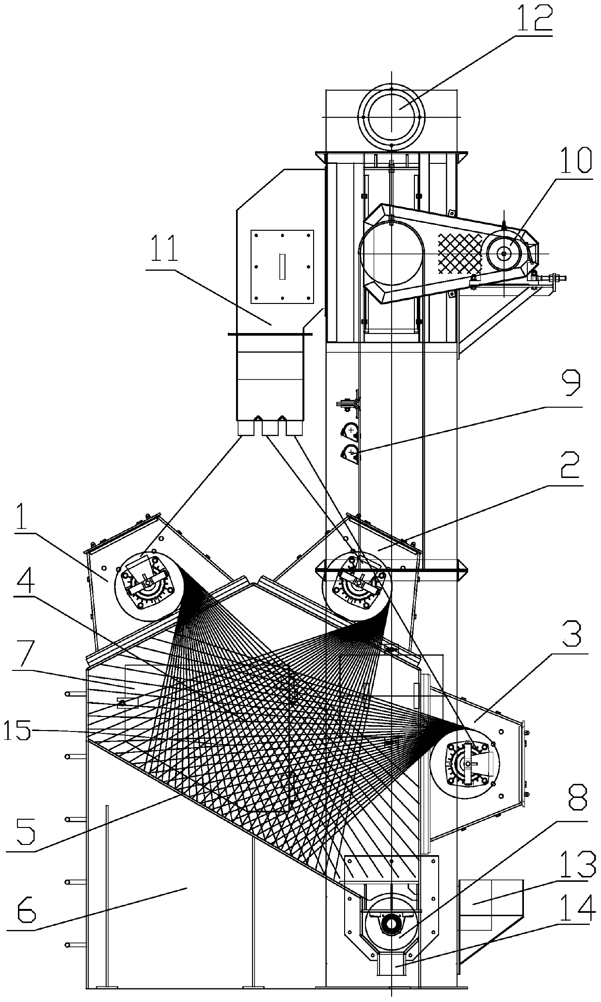
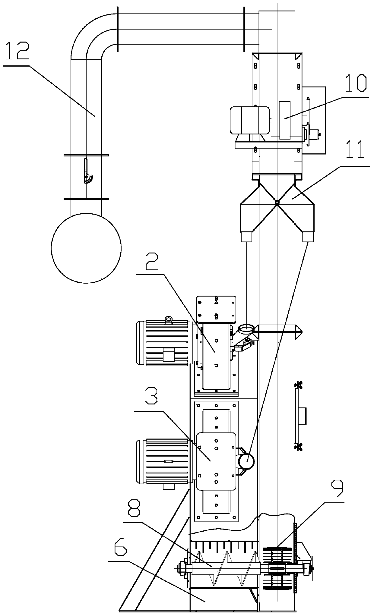
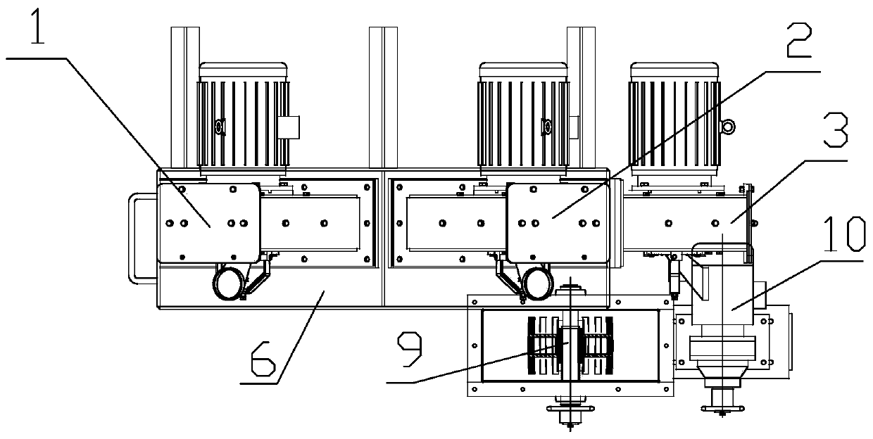
[0019] Such as Figure 1-3 As shown, the stainless steel wire cutting shot grinding machine mainly includes a shot blasting chamber 6 and a first blasting device 1, a second blasting device 2, and a third blasting device 3 installed on the blasting chamber; it also includes a screw conveyor Machine 8, bucket elevator 9, shot slag separator 11, stainless steel wire-cut shot feed port 13, stainless steel wire-cut shot discharge port 14.

[0020] The blasting direction of the first blasting device 1 and the second blasting device 2 is from top to bottom, and the blasting direction of the third blasting device 3 is from right to left. And the projecting lines of the three shot blasters intersect in an area, which is the shot collision area 15 . figure 1 The first blasting device 1 and the second blasting device 2 installed in the center are symmetrical along a vertical line, and the blasting ports of these two blasting devices are on the right side. The third blasting device 3 i...


PUM


Abstract

The invention discloses a stainless steel wire cut shot rounding machine and a rounding method, wherein the rounding machine comprises a shot blasting chamber and shot blasters arranged on the shot blasting chamber; the shot blasting chamber is internally provided with a protective plate. The stainless steel wire cut shot rounding machine is characterized in that the three shot blasters are respectively a first shot blaster, a second shot blaster and a third shot blaster, when the first shot blaster and the second shot blaster blast from top to bottom; the third shot blaster blasts from right to left; the blasting lines of the three shot blasters are crossed in one area which is a cut shot collision area; the shot blasting chamber is internally provided with an oblique protective plate below the short blasters, and the oblique protective plate is high in left end and is low in right end; projection is carried out along the normal direction perpendicular to the oblique protective plate, so that the cut shot collision area projects at the middle part or the middle upper part of the oblique protective plate. The stainless steel wire cut shot rounding machine and the rounding method, which are provided by the invention, are high in rounding efficiency, and the equipment loss is low.

Description

technical field [0001] The invention relates to the technical field of stainless steel wire-cut shot production, in particular to a stainless steel wire-cut shot rounding machine and a rounding method. Background technique [0002] Stainless steel wire cut shot is made of stainless steel wire after drawing, cutting, and rounding. Since the surface of the steel shot has edges and corners after cutting, it is easy to damage the surface flatness of the workpiece after throwing, and affect the surface quality. The workpiece needs to be rounded before throwing. The traditional stainless steel wire-cut shot rounding is a shot blasting machine that throws the stainless steel wire-cut shot on the wall guard plate of the shot blasting chamber. Round. This rounding method has long rounding time, low production efficiency, and large equipment loss. Contents of the invention [0003] In order to overcome the above-mentioned shortcomings in the prior art, the object of the present in...

Claims


Application Information

Patent Timeline
Patent Type & Authority Applications(China)
IPC IPC(8): B24C3/02B24C7/00B24C9/00
Inventor 邢向涛张来斌张守全韩涛李长春王瑞国
Owner 山东开泰工业科技有限公司
Learn More