Molding die and molding method

A molding method and mold technology, applied in the direction of coating, can solve problems such as difficulty in ensuring product rigidity, and achieve the effect of improving appearance and shape

Inactive Publication Date: 2014-08-13
SUZUKI MOTOR CORP
View PDF7 Cites 4 Cited by
  • Summary
  • Abstract
  • Description
  • Claims
  • Application Information

AI Technical Summary

Problems solved by technology

Therefore, for automotive interior resin parts, there is a method of reducing the thickness of the part to achieve weight reduction, but it is difficult to ensure the rigidity of the product when reducing the thickness of the product

Method used


Image

  • Molding die and molding method
  • Molding die and molding method
  • Molding die and molding method

Examples


Embodiment

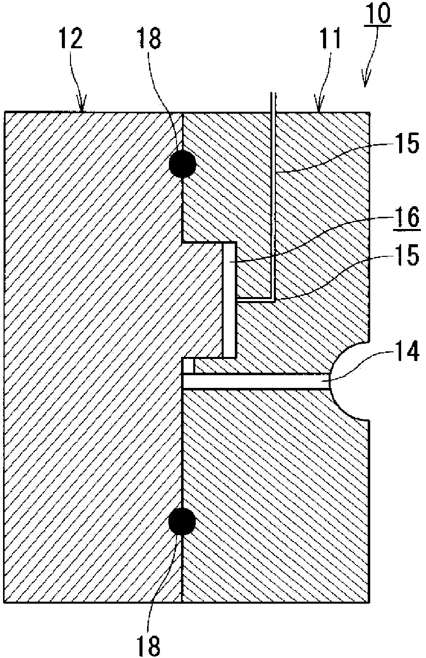
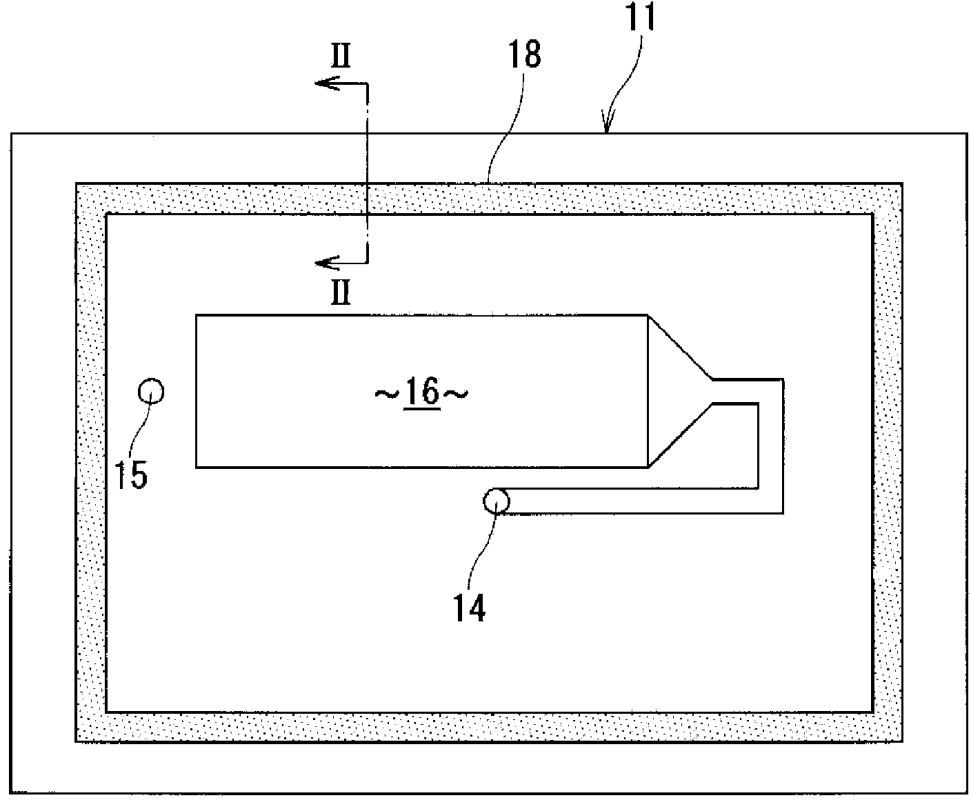
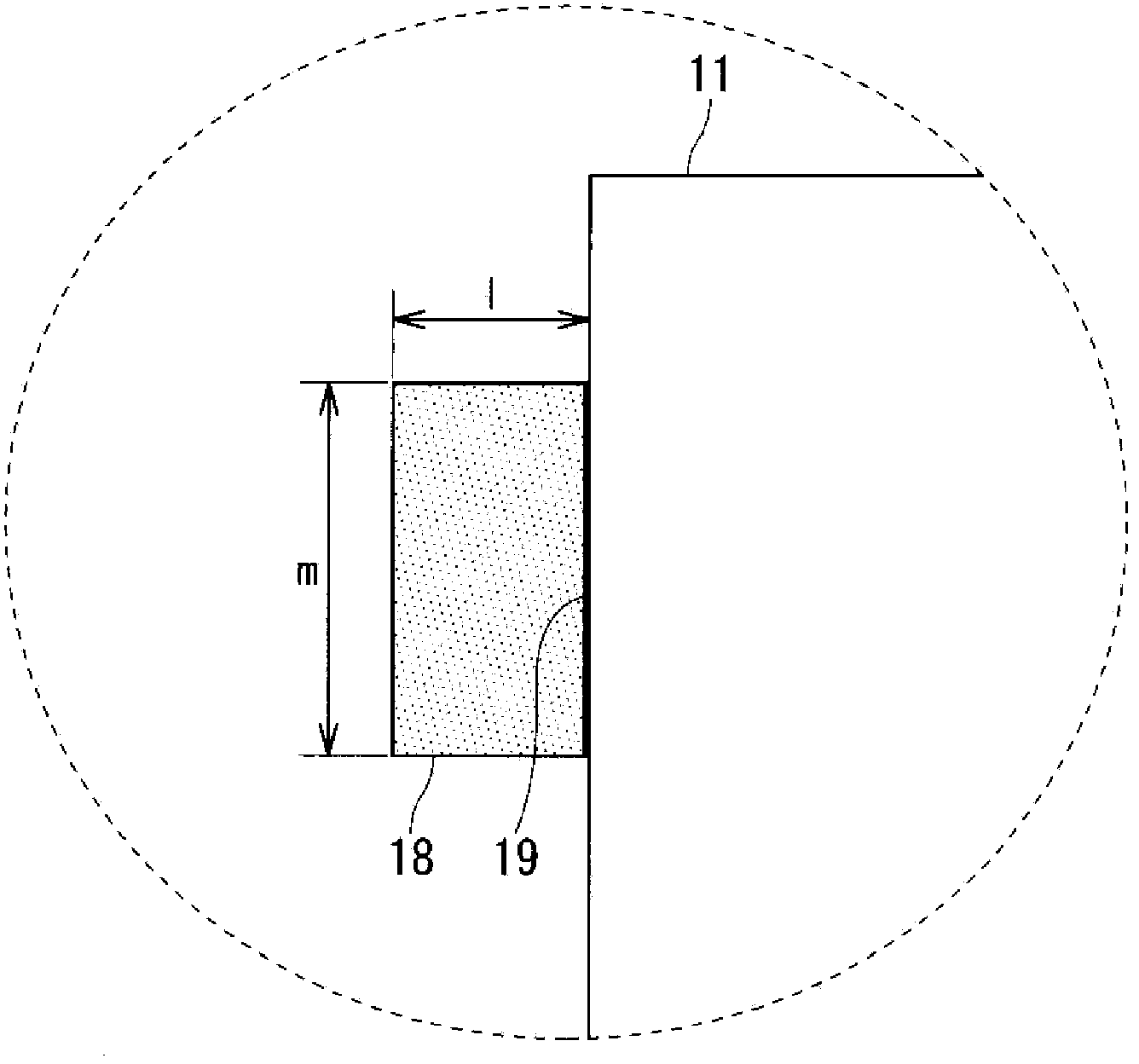
[0069] Injection foam molding can be performed by attaching the molding die 10 to an injection molding machine (not shown). Such as Figure 8 As shown, when the forming mold 10 is closed, the fixed mold 11 and the movable mold 12 are clamped, as Figure 9 As shown, the continuous air cells of the closed-loop seal 18 are collapsed to obtain a sealed configuration. When the air is supplied from the white air supply and discharge holes 15 , even if the molten resin is injected into the mold cavity 16 , it is possible to apply a pressure to prevent the molten resin from breaking.

[0070] In addition, if Figure 10 As shown, when the forming mold 10 is opened by using the reverse action of the core, the sealing member (elastic foam) 18 with open cells and rubber elasticity can release the residual air due to the property of the open cells with elastic recovery force. It is discharged from the inside of the mold 10 to the outside.

[0071] As a result, the remaining air in the ...


PUM


Abstract

A molding die for molding a foam molding in a cavity constituted in the interior by matching a stationary die and a movable die, the cavity being able to be filled with molten resin, and the foam molding being produced using counter-pressure. A seal material for sealing the pressurization area for the counter pressure technique between the stationary die and the movable die is provided to the molding die, and the seal material is constituted of an elastic foam that has open cells.

Description

technical field [0001] The present invention relates to a molding die and a molding method that prevent appearance defects during foam molding and improve the appearance shape of a foam molded product. Background technique [0002] In recent years, in order to reduce CO emitted from automobiles 2 In order to improve fuel economy, it is necessary to reduce the weight of automobiles. Therefore, for automotive interior resin parts, there is a method of reducing the thickness of the part to achieve weight reduction, but it is difficult to ensure the rigidity of the product when the product is thinned. [0003] On the other hand, there is injection foam molding using a molding die as a method of reducing the weight of a product while ensuring rigidity. Injection foam molding is a method in which a foaming agent is added to PP resin, molten resin is injected into the molding space (cavity) of a molding mold, and then the movable mold of the mold is moved (core reverse movement (...

Claims


Application Information

Patent Timeline
Patent Type & Authority Applications(China)
IPC IPC(8): B29C45/00B29C45/26B29K105/04
CPCB29C44/42B29C45/26B29C45/00B29C44/588B29C33/0038
Inventor 江川贵久
Owner SUZUKI MOTOR CORP
Why Eureka
Try Eureka