
Hollow ultrasonic motor allowing stator to float

An ultrasonic motor and stator technology, applied in the field of electronics, can solve the problems of limited motor design space, low efficiency, small inner hole of hollow motor, etc., and achieve the effect of stable motor operation, favorable processing and assembly, and high linearity.

Inactive Publication Date: 2014-08-13
NANJING UNIV OF AERONAUTICS & ASTRONAUTICS
View PDF5 Cites 3 Cited by
  • Summary
  • Abstract
  • Description
  • Claims
  • Application Information

AI Technical Summary

Problems solved by technology

[0013] The purpose of the present invention is to aim at the low efficiency of converting electrical energy into mechanical energy due to the connection between the stator and the base of the existing hollow ultrasonic motor by means of screws or clamping structures; Image 6 ) makes the inner hole of the hollow motor smaller, which limits the design space of the motor. A hollow ultrasonic motor with axially floating stator is designed.

Method used


Image

  • Hollow ultrasonic motor allowing stator to float
  • Hollow ultrasonic motor allowing stator to float
  • Hollow ultrasonic motor allowing stator to float

Examples


Embodiment Construction

[0033] The present invention will be further described below in conjunction with the accompanying drawings and embodiments.

[0034] Such as Figure 1-4 shown.

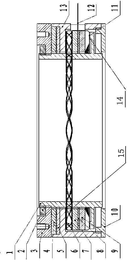
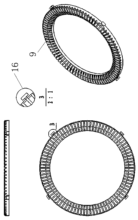
[0035] A hollow ultrasonic motor with a floating stator, which includes a rigid rotor 1, a lock nut 2, a preload nut 3, and a thrust bearing 4 (such as Figure 5 ), wear-resistant sheet 5, wave spring 6, insulating pad 7, piezoelectric ceramic sheet 8, stator 9 (such as figure 2 ), end cover 10, friction plate 11, flexible printed board 12 and base 13, such as figure 1 shown. Both the lock nut 2 and the preload nut 3 are screwed on one end of the rigid rotor 1, one end surface of the lock nut 2 is against the one end surface of the preload nut 3 to prevent its axial movement, and the other end of the preload nut 3 Supported on the thrust bearing 4 so that the preload nut 3 can rotate synchronously with the rigid rotor 1, the thrust bearing 4 is installed on one end of the base 13, and the end cover 10 is install...


PUM


Abstract

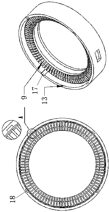
A hollow ultrasonic motor allowing a stator to float comprises a rigid rotor (1), the stator (9) and a base (13). A locking nut (2) and a pre-compression nut (3) are both rotatably installed to one end of the rigid rotor (1). A thrust bearing (4) is installed to one end of the base (13). The hollow ultrasonic motor is characterized in that the rigid rotor (1) is sleeved with the stator (9), a piezoelectric ceramic piece (8) and an insulating pad (7); the driving end face of the stator (9) makes contact with a friction plate (11) and drives the rigid rotor to rotate through frictional force; the other end face of the stator (9) makes contact with the piezoelectric ceramic piece (8); a rotation prevention structure (16) for preventing relative rotation is arranged between the stator (9) and the base (13). According to the hollow ultrasonic motor, the connection between the stator and the base is transformed into sliding chute fit so that the stator can float up and down; in this way, the conversion efficiency of electric energy is higher, and an inner hole of the motor can be larger.

Description

technical field [0001] The invention relates to electronics, in particular to a hollow ultrasonic motor driven by deformation of piezoelectric ceramics, in particular to a hollow ultrasonic motor with a floating stator. Background technique [0002] Ultrasonic Motor (Ultrasonic Motor) is a new concept power device developed in the past two decades. It breaks through the concept of traditional electromagnetic motor. It has no winding and magnetic circuit. It does not rely on electromagnetic interaction to convert energy to generate rotor motion, but Using the inverse piezoelectric effect of the piezoelectric material and the ultrasonic vibration of the elastic body, the small deformation of the material is converted into the macroscopic motion of the rotor or mover (slider) through the resonance amplification of the elastic body and friction transmission. The hollow traveling wave ultrasonic motor is a kind of motor in which the stator, rotor, base and other core componen...

Claims


Application Information

Patent Timeline
IPC IPC(8): H02N2/10H02N2/12
Inventor 牛子杰孙志峻张军
Owner NANJING UNIV OF AERONAUTICS & ASTRONAUTICS
Learn More