
Corestone compaction device

A compaction device and core technology, applied in the direction of forming indenters, etc., can solve the problems of decreased experimental quality and uneven stress on the core, and achieve the effects of easy transportation, increased success rate, and good structure.

Active Publication Date: 2014-08-13
HENGYE ELECTRONICS JIAXING CITY
View PDF8 Cites 7 Cited by
  • Summary
  • Abstract
  • Description
  • Claims
  • Application Information

AI Technical Summary

Problems solved by technology

[0003] The object of the present invention is to provide a rock core compacting device, which is used to solve the problem that the core is unevenly stressed when making the rock core at present, which leads to the problem that the quality of the experiment is reduced

Method used


Image

  • Corestone compaction device
  • Corestone compaction device

Examples


Embodiment Construction

[0016] The present invention will be further described below in conjunction with the accompanying drawings.

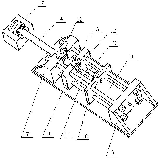
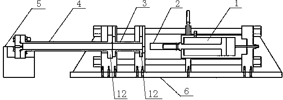
[0017] combine figure 1 , figure 2 As shown, this core compacting device includes a frame seat 6, a plunger type hydraulic cylinder 1, a filler pipe 3, a sand filling pipe 4, and a rear bracket 5 for the sand filling pipe. The two ends of the frame seat 6 have supports, two There are two support plates in the middle of the support, and the support at both ends and the two support plates are tightened by four steel columns to bear the pressure, and the support at both ends and the two support plates are used with the bottom plate of the frame seat. Tighten the large screw in place.

[0018] The front end of the plunger hydraulic cylinder 1 is located in the rear support plate 10, the plunger head is provided with a compaction head 2, and the scale line 11 is set on the compaction head 2, and the rear end of the plunger hydraulic cylinder 1 just sits on the rear suppo...


PUM


Abstract

The invention relates to a corestone compaction device. The corestone compaction device comprises a frame base, a plunger type hydraulic cylinder, a filling tube, a sand-filled tube and a sand-filled tube rear bracket. The plunger type hydraulic cylinder is horizontally located at the rear end of the frame base, a compaction head is arranged at the front end of a plunger of the plunger type hydraulic cylinder, and the compaction head is provided with scale marks. The sand-filled tube is connected and communicated with the filling tube, the filling tube is arranged corresponding to the compaction head, and the sand-filled tube, the filling tube and the compaction head are placed in the same horizontal axis. The rear end of the plunger type hydraulic cylinder is just positioned in a frame base rear support, and the front end of the plunger type hydraulic cylinder is placed in a rear supporting plate. A U-shaped groove is formed in a frame base front support, and a U-shaped groove is also formed in a front supporting plate. The two ends of the filling tube and the two ends of the sand-filled tube are respectively provided with a flange, the flange at one end of the filling tube is placed in the U-shaped groove of the frame base front support, and the flange at the other end of the filling tube is placed in the U-shaped groove of the front supporting plate. The flange at the front end of the sand-filled tube is mounted on the sand-filled tube rear bracket, and the flange at the rear end of the sand-filled tube is placed in the U-shaped groove of the frame base front support. By means of the corestone compaction device, one-time even corestone compaction can be achieved, and the diameter of the filling tube and the diameter of the sand-filled tube cannot be limited.

Description

technical field [0001] The invention relates to the technical field of rock core compaction during experimental rock core processing, in particular to a rock core compaction device. Background technique [0002] In today's petroleum experiments, the use of cores is indispensable, so the requirements for cores are getting higher and higher. For the cores used in the past, due to the uneven pressure distribution of the cores and the inability to be compacted at one time, the core compaction In the process, once compacted, it is necessary to add another filler to the sand filling pipe, resulting in a decrease in the quality of the core, which misleads the results of the experiment, fails to analyze the experimental data better, and eventually deviates the results and leads to the failure of the experiment. Not only consumed energy but also wasted time and materials. In addition, most of the common rock cores on the market cannot withstand high temperature and high pressure. ...

Claims


Application Information

Patent Timeline
Patent Type & Authority Applications(China)
IPC IPC(8): B28B3/04
CPCB28B3/04
Inventor 王春生田明磊刘欢冯翠菊王旭王岩
Owner HENGYE ELECTRONICS JIAXING CITY
Learn More